


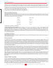
System 10 InWall Speakers
● ● ● ● ● ● ● ● ● ● ●
8
● ● ● ● ● ● ● ● ● ● ●
Dimensions 17 1/4"H x 8 7/16"W x 3 5/8"D
Cut-out Dimensions 15 13/16"H x 7"W
Optimum wall volume 0.5 - 1.25 cu. ft.
Orientation Vertical (Portrait)
Drivers/Design 2 - 6.5" IMG woofers
1 - 1" Silk dome tweeter
D'Appolito array
Frequency Response 46 - 20kHz +/- 3dB
Sensitivity 89dB
Impedance 6 Ohms
Crossover Frequency 3400Hz, 4th order Linkwitz-Riley
Companion Components Subwoofer(s):
4.5 PBM, 172 PBM, 272 PBM
Surround(s):
System 10 SR, 4.5 SR, 174 SR,
274T SR, System 20 SR
Mounting Brackets for
Surround Speakers 174 SR = IN-RF BRK (no trim kit)
274 T = 274 IN-RF (w/trim kit)
New Construction Kit IN-NC-10
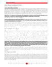
System 10 LCR InWall Enclosure Recommendations
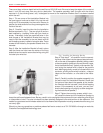
Please use this information to construct an in-wall enclosure if you so desire.
Doing so will generally improve the performance and increase the power handling
of the system. We have not included information for the System 10 SR since one
of its woofers is self-enclosed and the other will not generate anywhere near
the bass energy the LCR system will.
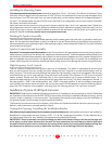
Be sure to line the cavity with weatherproof insulation, being careful to avoid
letting the insulation touch the backs of the woofer cones. It’s also important to
seal the joints of the enclosure with a high quality non-shrinking caulk.
Be careful to keep the wires from touching the chassis of the drivers or baffle in
such a manner that the wire might vibrate and buzz. You may use nylon wire ties
to keep the wires properly positioned. Such ties are available that are designed
to screw directly to studs making them ideal for this purpose.
As always, take care to wire the speakers properly, with the positive lead (normally
marked with a red terminal or a “+” sign) from the amplifier connected to the
positive terminal on the speakers and the negative (marked with a black terminal
or a “-” sign) connected to its respective terminals.
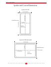
010-1164
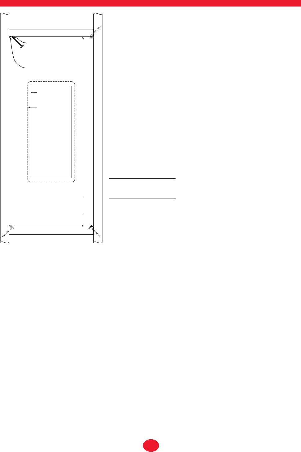
Toe nail or screw
to hold firebock
in position until
sealant dries.
Seal edges with
caulking
Mounting Hole
Outline
Speaker Frame
Outline
Proportions illustrated are for 16"
on-center 2" X 4" stud installation.
See table below for proper dimensions.
See table
for proper
dimension
2 x 4 Construction 1ft
3
1.25ft
3
16" O.C.Studs 34" 42.5"
24" O.C. Studs 22" 27.5"
2 x 6 Construction 1ft
3
1.25ft
3
16" O.C.Studs 21.7" 27"
24" O.C. Studs 16"* 17.5"
* Minimum cut out height is 15.8".
Placing the fire block at 16" yields
an internal volume of 1.15ft
3
.
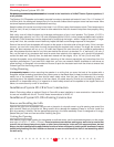
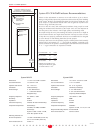
System 10 LCR System 10 SR
Dimensions 12 1/16"H x 15 5/8" x 3 5/8"D
Cut-out Dimensions 11"H x 14 3/8"W
Optimum wall volume 0.5 cu. ft. or greater
Orientation Horizontal (Landscape)
Drivers/Design 2 - 4.5" IMG woofers
2 - 3/4" soft dome tweeter
Frequency Enhanced Dipole
Frequency Response 100 - 20kHz +/- 3dB
Sensitivity 88dB
Impedance 6 Ohms
Crossover Frequency 5000Hz
Companion Components Satellites:
System 10 LCR, 171 LR, 271 LR
Required Mounting Bracket IN-INST-20SR
New Construction Kit Same as above