


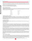

System 10 InWall Speakers
● ● ● ● ● ● ● ● ● ● ●
6
● ● ● ● ● ● ● ● ● ● ●
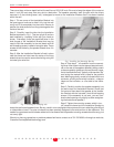
There must be a minimum depth behind the wall face of 3 5/8 (92 mm). Be sure to keep the edges of the cutout at
least 1 inch (25 mm) away from any stud or obstruction. The speaker assembly itself (the part with the drivers
mounted in it, the trimming bezel, etc.) is designed to mount to the Installation Bracket after it has been installed
within the wall.
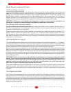
Step 1. Tilt one corner of the Installation Bracket into
the opening and continue to slide it fully into the wall
cavity until it fits completely into the cutout. Be sure to
position the side extensions so they press against the
inside of the wall.
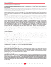
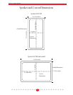
Step 2. Carefully insert the tabs into the Installation
Bracket as shown in Fig. 1. They are a tight fit and are
best installed by “clamping” them with your hand as
shown. Alternately, there are predrilled holes in the
side flanges of the Installation Bracket that may be
used to hold the assembly to the wall board with #6
self-threading screws, instead of using the tabs. These
screws will be hidden by the speaker’s bezel when it is
mounted.
Step 3. After the Installation Bracket is fixed in place
note that there are holes near the center of the long
sides that can be used to secure feed wiring using the
included nylon wire ties.
Step 4. Strip about ˚” of insulation from the connect-
ing wires. Insert them into the appropriate push termi-
nal on the rear of the speaker assembly, being careful
to observe polarity (positive to the red terminal, nega-
tive to the black terminal). Typically, with standard “zip”
cord wiring the marked wire is used for the positive
lead. Markings typically consist of a thread within one
conductor, printing on the wire’s insulation, a ridge or
ridges on the insulation, or a flat side to the insula-
tion.
Step 5. Carefully position the speaker assembly into
the wall cutout and Installation Bracket. Check that
it’s level and then attach the speaker to the Installa-
tion Bracket with the included 3 inch #6 self-tapping
screws. (If the assembly is not level, you can over-
size the wall opening very slightly to allow straighten-
ing the bracket and speaker.)
Step 6. Tighten the mounting screws, which in turn
will cause the bezel and the Installation Bracket to
clamp the wall board between them.
Be very careful not to overtighten the screws as this can make the grille difficult
or impossible to install. The outer trim bezel has been specially designed to flex and conform to the wallboard. This
makes for a good seal and eliminates rattles but it also means that the speaker mounting screws should be snug, but
not overly tight.
Should you have any questions or problems please feel free to contact us at 781-762-6300 or through our web site,
Customer Service@atlantictechnology.com.
Fig. 2 Installing the clamping tabs
Fig 1 Installing the Mounting Bracket