


System 10 InWall Speakers
● ● ● ● ● ● ● ● ● ● ●
5
● ● ● ● ● ● ● ● ● ● ●
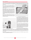
Installing the Mounting Frame
The clamping mechanism allows the wall material to range from 1/2 to 1 1/2 inches (12 to 38 mm) in thickness. There
must be a minimum depth behind the wall face of 3 5/8” (92 mm). As noted above, be sure to keep the edges of the
cutout at least 1 inch (25 mm) away from any stud or obstruction, as the rotating clamps will not operate properly if
you don’t. The speaker baffle (the part with the drivers mounted in it) is designed to mount into the white frame after
the frame is mounted into the wall.
Insert the frame into the cutout and using a level or square carefully align it so it is (or it appears) level. Tighten the
mounting screws, which will cause the clamps to rotate and position themselves properly behind the wall, until the
frame is just snug in the wall. You want the bezel to conform to the wall board, and the frame not to rattle from the
speaker’s vibration but be very careful not to overtighten the screws.
Painting the Speaker Assembly
The white plastic frame of the speaker baffle assembly and the metal grille may be left as is, or painted to match your
décor. You can paint the frame before or after it is installed in the wall. Spray painting (using slightly thinned paint) is
the best method to use for painting the grille. After painting the grille, use air pressure to “blow out” any grille holes that
are covered over with paint.
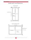
Speaker Connection and Assembly
Strip about ˚” of insulation from the connecting wires. Connect them to the appropriate push terminal, being careful to
observe polarity (positive to the red terminal, negative to the black terminal). Install the speaker baffle assembly into
the previously mounted frame assembly, being careful to ensure that the speaker wire isn’t pressed up against the
back of a speaker cone, and screw it into place using the supplied screws. Again, be careful not to overtighten the
screws. Insert the grille into the frame as outlined above, being careful not to damage the frame or the grille’s finish.
High Frequency Level Control
There is a switch located behind the grille on the front of the speaker. This switch is accessible by removing the
grille as outlined above. You can change the switch setting with your fingernail or a small pointed object, such as
a ball point pen. The switch has three settings that adjust the high frequency output from the speaker. We strongly
recommend that you try all three settings, using both music and movies (if the System 10 LCR is part of a home
theater system). Please note that recordings vary in their sound balance so try several different discs. Try to
achieve the best balance of natural overall sound with good detail and clarity. The switch settings are “Normal” in
the lower position, “-2dB” in the middle position, and “+2dB” in the upper position. To aim the tweeter, press gently
on the plastic ring that surrounds the dome, but not the dome itself. Aim the tweeter at the prime listening position
when the LCR is used as a front speaker, and away from the listening position if it’s used as a surround.
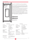
Installation of System 10 SR Dipole Surround
IMPORTANT:
Note that the Installation Bracket is required for all installations, new construction or retrofit. Please see
the installation instructions for the IN-INST-20SR for information pertaining to Installation Bracket mounting, and its
use as a rough-in assembly in new construction. The following instructions primarily apply to the final installation of
the speaker system into the already mounted Installation Bracket.
The following instructions cover only the System 10 SR. When the Installation Bracket has been used as a rough-in
device in new construction, proceed directly to Step 4.
Cutting the Opening - Installing the Installation Bracket
After determining the best location for the speaker as outlined above, use the template (enclosed in the Installation
Bracket kit) to cut the proper size hole. (System 10 SR - 11” x 14 3/8”, “landscape” orientation).
It’s very important to cut
the hole level as there is no “play” between the speaker and the Installation Bracket.
IMPORTANT: Exercise extreme care before making any wall cuts to ensure that you will not cut through any
wires, pipes, or other items that may be in the wall. You may sometimes, but not always, be able to determine
the approximate location of wires and pipes by looking at the locations of nearby outlets and plumbing. But
their presence or absence is never an assurance that there is not something within the wall cavity.