


6
AT-1 High Performance Loudspeaker with H-PAS™ Technology
Connecting Your Speakers
We recommend that you connect your system using high quality dual
conductor stranded wire of 16 gauge or heavier, for lengths up to 25 feet
(8m) . Remember, the lower the gauge number, the heavier the wire. Use
heavier gauge wire for longer runs. Please contact your audio/video dealer
or installer for specific cable recommendations and further information
regarding special circumstances.
The terminals themselves are designed to allow the use of very heavy
speaker wire or connectors. Be sure to tighten them securely, but don’t
over-tighten them.
WARNING:
To prevent risk of electrical shock or damage to your
equipment, always switch off the amplifier or receiver when making
any system connections.
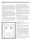
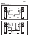
Conventional Connection
Leave terminal straps in place. (See figure 6 opposite)
You can connect your speakers by using a variety of audio connectors such
as pin connectors, spade lugs, etc., or you can:
1. Remove ½" (13mm) of insulation from each wire end.
2. Twist the stranded wire together, keeping the two ends
separate.
3. Place the appropriate wire through the postholes in the
connectors. These holes are revealed when you loosen the
connector’s capscrew.
4. Screw down the capscrew tightly, but be careful not to over
tighten it.
5. Check the tightness of the capscrews 24 hours after hookup
and occasionally after that, as they can loosen over time.
It’s important to observe polarity while making speaker connections: red
(+) terminals on the amplifier to red (+) on the speaker, black (–) on the
amplifier to black (–) on the speaker. Look carefully at the wires you are
using and note that one of the conductors of each pair will typically be
identified by color, printing on the outer jacket, ridges on the outer jacket,
or a thread intertwined with the wire strands. By convention, the marked
wire is connected to the red (+) terminal.
WARNING:
Before turning on the amplifier, be certain that no stray
wire strands are touching across any terminals as this might damage
your amplifier.
Finally, check the polarity of your speakers by listening to some stereo music
with good bass content. If the sound seems “hollow”, unusually spread out,
or seems to have weak bass, recheck your connections for proper polarity
and correct the out of phase connection, if necessary.
Bi-amp Connection
Remove terminal straps. (See figure 7 opposite)
Bi-amplification uses separate amplifiers for the high- and low-frequency
sections of the speaker. Using separate amplifiers increases the current avail-
able to drive the speaker and decreases the audibility of amplifier-generated
harmonic and intermodulation distortion, since the amplifiers’ high- and
low-frequency distortion products do not interact with each other the way
they do in a single full-range amplifier. A speaker driven in bi-amplified
mode will play louder and sound cleaner than the same speaker driven by
a single full-range amplifier of equivalent combined wattage.
IMPORTANT:
The power recommendation for these speaker systems
assumes that you will not operate your amplifier/receiver in a way
that produces distortion. Even rugged speakers like these can be dam-
aged by an amplifier driven into audible distortion. The harsh ampli-
fier distortion (“clipping”) that occurs in this situation will eventually
cause damage to the speaker system. This type of damage may be
cumulative and can build up over time, as the amplifier is driven into
overload again and again. Such damage is easily identifiable through
examination of the damaged speaker’s voice coil and is not covered
by the warranty.
These speakers will play very loudly when provided with enough undis-
torted power to do so. If necessary, consult your dealer or Atlantic Technol-
ogy for additional information.
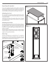
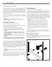
Wire Management System
Attach the wire management guides to the speaker’s rear panel as shown
(see figure 5) with the included hardware. Run your speaker wire under the
guides for a neat installation.
Connecting Your Speakers
Figure 5
Installing the wire management brackets