


Operating Manual - XR1001, XR2001, and XR4001 Electronic Crossovers
6
6. AUDIO CONNECTIONS AND CABLES
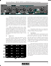
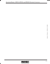
6.1 Balanced
Your crossover is provided with two different
connector types, wired in parallel. 1/4 inch stereo phone
jacks and three pin XLR type connectors will allow inter-
facing to most professional audio products, with pin 2 hot
(+) and pin 3 (-). The inputs and outputs can be used ei-
ther balanced or unbalanced. We recommend balanced
connections between all components in your system, as
this minimizes ground-loop or induced hum and noise.
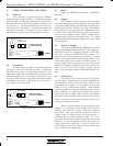
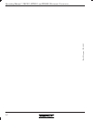
6.2 Unbalanced
If either inputs or outputs are used unbalanced,
the signal is on the (+) connection and the (-) connection
must be tied to ground. A mono phone plug used as an
unbalanced connection will automatically ground the ring
of the jack which is the (-) connection. When using a ste-
reo plug or XLR connector for unbalanced input or output
connections, the signal (-) MUST be tied to ground, or
loss of signal level may result.
6.3 Inputs
Inputs are 20KΩ active balanced, or 10KΩ un-
balanced.
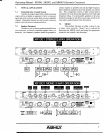
6.4 Outputs
The outputs on Ashly crossovers are low imped-
ance (200 ohms typical) pseudo-balanced type using both
a 3-pin male XLR connector and standard 1/4" phone jack.
Pseudo-balanced lines, while not carrying a truly differ-
ential signal, have an equivalent line impedance on both
(+) and (-) lines. This allows for long cable runs from the
crossover into balanced inputs without compromising
common mode rejection of unwanted noise. To realize
maximum headroom, terminate outputs into loads of 600
ohms or greater.
6.5 Mono Low Output
Ashly models XR2001 and XR4001 have an ad-
ditional jack labeled MONO LOW OUT. This output rep-
resents the sum of low frequency outputs of both chan-
nels, and is a function of BOTH low level controls. It is
typically used for driving mono sub-woofers in a stereo
system, reducing the number of power amps needed. Con-
nectors and wiring are the same as the other outputs. If
you are using a mono low output, you may also use the
normal low frequency outputs to drive other speaker sys-
tems; any or all of the low frequency outputs may be
used at any given time without interaction between out-
puts.
6.6 System Phase
The outputs of all Ashly crossovers are in phase
with the input. Assuming that your power amplifiers do
not invert phase (most do not), the signals from all your
amps should be in phase. If all speakers are the same
brand, it is easy to keep them in phase. With different
brands of speakers used together, phasing becomes a little
more confusing. It is important to keep all the speakers
within each band in phase with each other, and equally
important to keep all bands of the system in phase as well.
If this is not done, loss of level and pattern control at the
crossover frequency will result.
Phase of CONE speakers can be checked by con-
necting a 1.5 volt battery to the speaker and observing
which way the cone moves. Don’t try this with compres-
sion drivers! The most common convention is that (+)
voltage on the (+) terminal moves the cone forward. A
notable exception to this convention is JBL. A (+) volt-
age on the red terminal of a JBL speaker moves the cone
backward. If all your speakers are the same brand, just
connect them all the same way; if not, it’s best to test.
Unfortunately, compression drivers cannot be tested this
way. Ask the driver manufacturer.
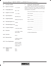
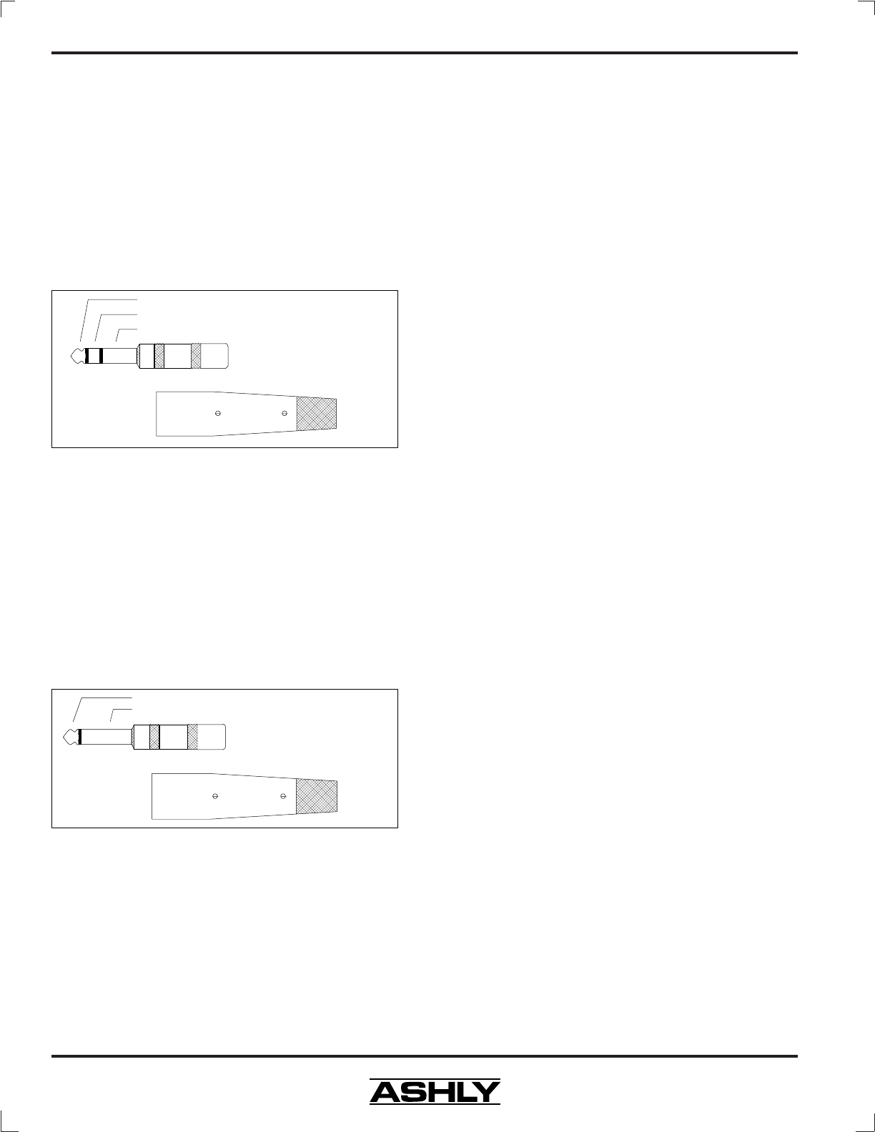
Stereo Phone Plug
used for balanced
Tip (+)
Ring (-)
Sleeve (Ground)
Pins are
numbered
in the
connector
insert.
XLR Male
2 = (+)
3 = (-)
1 = (gnd)
Balanced Audio Connectors
Mono Phone Plug
used for unbalanced
Tip (+)
Sleeve (Ground)
Pins are
numbered
in the
connector
insert.
XLR Male
2 = (+)
3 = (gnd)
1 = (gnd)
Unbalanced Audio Connectors