


Operating Manual - XR1001, XR2001, and XR4001 Electronic Crossovers
4
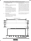
To allow a wider tuning range, our crossovers use
a recessed range switch for each frequency control. LED
indicators provide range status as soon as the unit is pow-
ered on. The range switch divides the frequency indi-
cated on the frequency control by 10 and gives a total
range of 200:1 for each control. Avoid accidental dam-
age to speakers by muting the outputs before changing
the range switch. Carefully plan and check the frequency
range selected to each driver before sending audio sig-
nals to your speakers.
The choice of crossover frequencies depends on
the type of speakers being used, personal taste, room
acoustics, and many other factors. Experiment to see what
works best for you.
CAUTION: High frequency compression driv-
ers may be destroyed by the use of too low a crossover
frequency. Follow the driver manufacturer’s recommen-
dations carefully. Make sure the range switch is properly
set. You may want to install a security cover if the unit is
accessible to untrained people.
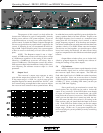
5.4 Response
This control, found adjacent to the crossover fre-
quency control, adjusts the damping of the filter affect
ing
the response shape of the filters at the crossover poin
t (see
drawing). The dial calibrations refer to the amount of at-
tenuation effected by the filter at the crossover frequency,
i.e., a setting of 3dB means that the filter’s high-pass and
low-pass outputs are each “rolled off 3dB at the crossover
point”. This describes Butterworth filter response, or a
gentle 3dB peak at the crossover point when the two filter
output signals overlap. To obtain a flat signal, or
“Linkowitz-Riley” response through the crossover region,
set the Response control to “6”. This attenuates each out-
put of the filter by 6dB at the crossover point (two identi-
cal signals added together yield a +6dB increase). To ob-
tain a notch at the crossover point, turn down the response
control past “6” to best suit your needs.
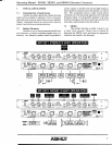
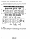
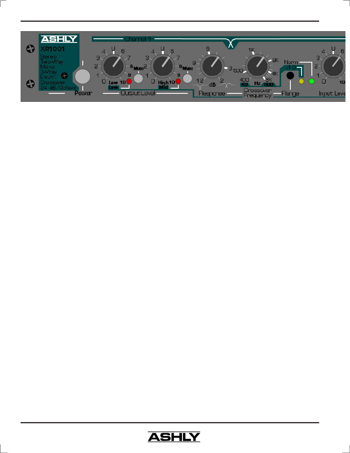
5. CONTROLS
Every Ashly crossover has the following controls:
a Power Switch, an Input Level control, a Crossover Fre-
quency (Hz) control and Range Switch for each dividing
point, a Response (dB) control, Output Level controls
with Mute Switches, and a Peak Indicator LED. The
XR1001 and XR2001 also have a Mode Switch for se-
lecting between 2-way and 3-way operation.
5.1 Power Switch
This switch connects AC power to the rest of the
unit. You will know power is on when one of the cross-
over frequency range LED indicators is lit. If there is no
light, check to see if the unit is plugged in to a live out-
let. If there is still no light, the internal AC line fuse may
have blown. Refer the unit to a qualified service techni-
cian for fuse replacement.
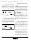
5.2 Input Level
This control can boost incoming signal up to
+8dB before it reaches the filters, or attenuate the signal
so that it is fully off. Maximum input level is +23dBu.
The “U” shown at the 12:00 position indicates “unity gain”
of the input section. We recommend setting this control
at unity and controlling system levels either prior to the
crossover or at the output level controls.
5.3 Crossover Frequency
This infinitely variable control allows you to se-
lect an appropriate crossover point for your speakers.
Turning the knob clockwise moves the crossover point to
a higher frequency, while turning it counterclockwise
moves it to a lower frequency. Crossover frequencies are
marked on standard ISO 1/3 octave center frequencies
with each octave calibrated. Calibration accuracy is very
good, typically within 1/3 octave or better. If greater
accuracy than this is necessary, measure the actual cross-
over frequency with an accurate oscillator/frequency
counter.