


5
Operating Manual - XR1001, XR2001, and XR4001 Electronic Crossovers
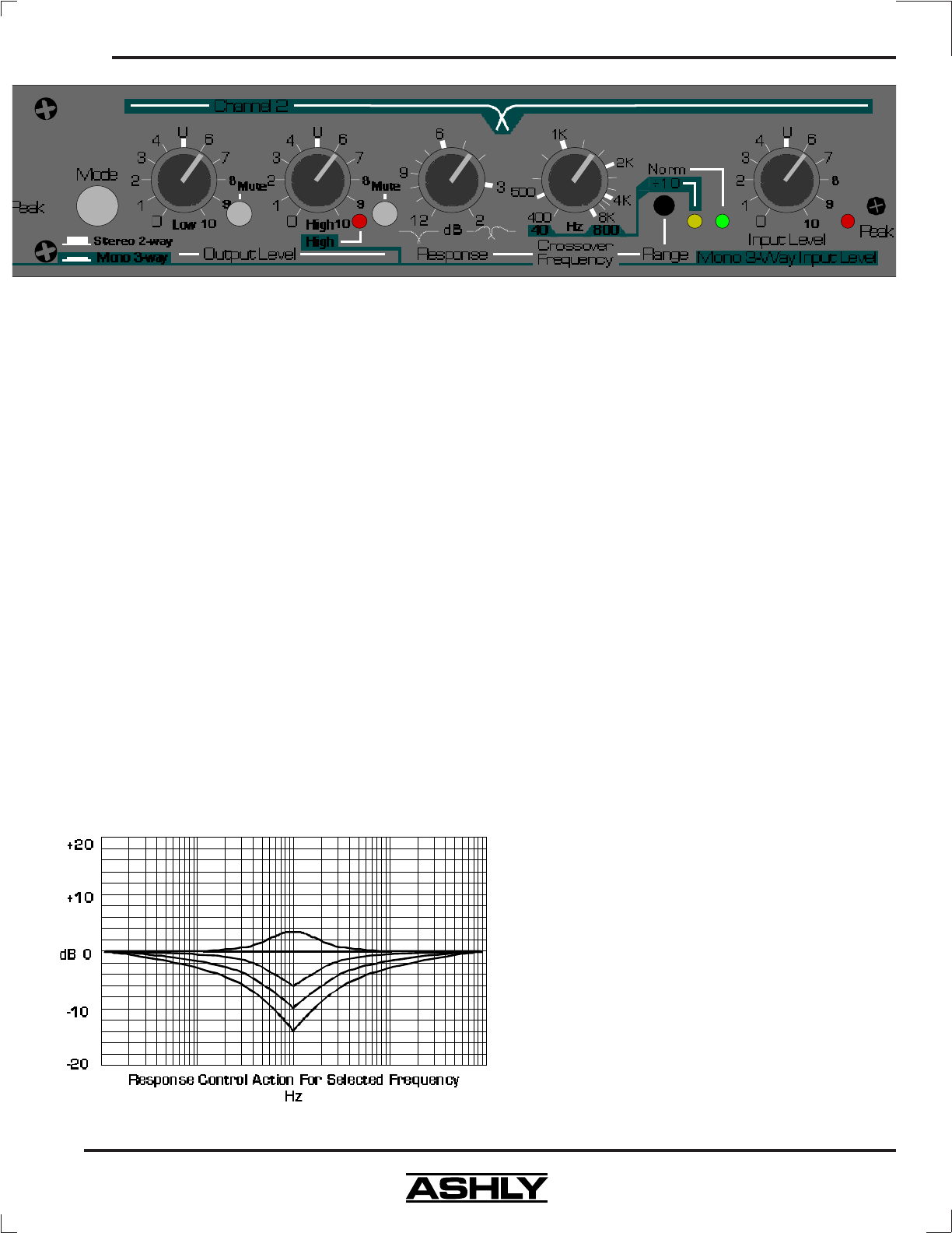
The purpose of this control is to help offset the
inaccuracies inherent in typical loudspeakers, thereby
helping you to achieve a flat system response. If you use
a spectrum analyzer to set up your system, adjust the re-
sponse control to obtain the flattest response through the
crossover region before any equalization is applied to the
system. If adjusting by ear, we recommend an initial set-
ting of 6dB. Adjust from this point if the system appears
to have an excess or deficiency of level at the crossover
point.
NOTE: The Response control is not a “slope”
control. A 12dB/octave crossover will always have a slope
of 12dB/octave regardless of the setting of this control.
Likewise, a 24dB/octave crossover will always have a
slope of 24dB/octave. The Response control only affects
filter response shape in the immediate vicinity of the cross-
over frequency; the ultimate crossover slope is a fixed
parameter.
5.5 Output Level
The crossover’s output stage operates at unity
gain with the output level controls set at “U”. Max gain
of the output stage is +15dB. In a typical setup, power
amplifier input level controls should be run “full-on”, with
level control being accomplished at the crossover. Adjust
the crossover level controls for best system balance. Keep
in mind that in any multi-amplified system, the higher fre-
quency speakers tend to be more efficient. Expect to run
the higher frequency level controls at a somewhat lower
setting than the low frequency level controls to obtain
proper frequency response. Note that horn and compres-
sion driver combinations are much more efficient than cone
speakers, often by 12 to 20dB! When cones and compres-
sion drivers are used together, you should expect a much
lower level setting for the horns (all other factors being
equal) to compensate for this difference and obtain proper
balance.
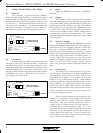
Output Mute switches allow you to isolate indi-
vidual or grouped outputs for listening tests without af-
fecting the settings of any other outputs.
5.6 Clip Indicator
Ashly crossovers feature a peak detection circuit
which monitors signal level at several critical points in
the crossover: input, filters, and outputs. The LED will
flash when signal levels of +20dBu are reached anywhere
in the crossover. Since our crossovers have a nominal
23dB of headroom referenced to a standard operating level
of 0dBu (.77 Volts), a flashing LED warns you that you
are only 3dB from clipping.
Since peak levels are monitored at several key
circuit points, the clip LED can be used to isolate the
source of any overload. If the LED flashes even though
all input and output levels are turned down, the signal
being fed to the crossover is excessive. If the LED flashes
when you turn the Input level control up (with the out-
puts still turned down), the overload is occurring in the
filter sections, and you should back the Input level down
a bit. If the LED first flashes when you turn the output
level controls up, then the overload is occurring in the
output stage. In this case, if your power amplifier con-
trols are at full gain, you are probably severely overdriving
your amplifier.