


Operating Manual - SRA-120 Power Amplifier
6
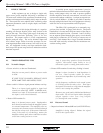
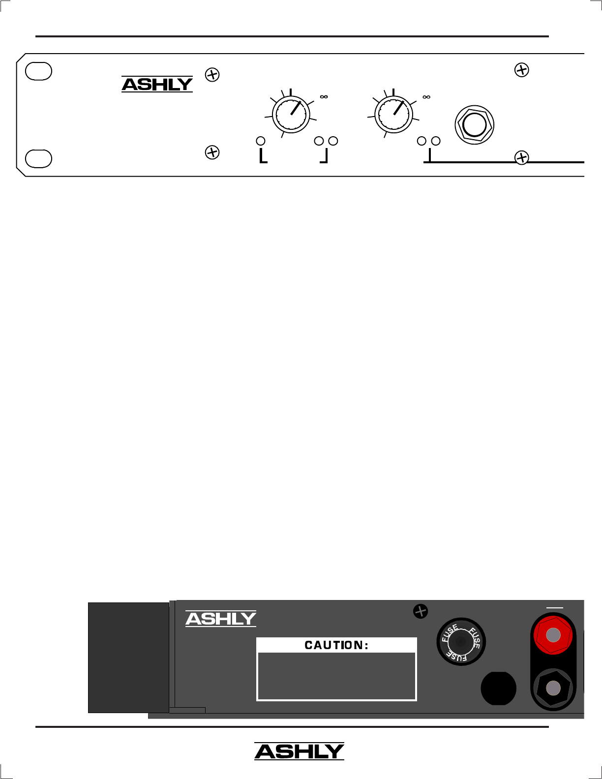
Sig.Clip
Protect
Sig.Clip
Stereo
Headphones
Channel 1
(Mono)
Channel 2
Level (dB) Level (dB)
-
0
-1
-3
-6
-10
-20
-
0
-1
-3
-6
-10
-20
SRA-120
Stereo
Power Amplifier
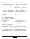
6.5 Protect Indicators
Protect mode in the SRA-120 is automatically
activated during extreme fault conditions, as well as dur-
ing power-up and power-down. When in protect mode, as
indicated by the red LED, the speaker output terminals
are internally disconnected. Conditions causing the am-
plifier to switch into protect mode include the following:
Turn-on delay/Instant turn off
Output short circuit
Load impedance below 2 ohms
DC at output (below 8Hz)
Ultrasonic signal (above 20KHz)
Amplifier overheating
Each channel automatically resets itself within
one second of removal of the fault condition. In the event
of overheating, it may take several minutes for the am-
plifier to reset. If thermal shutdown occurs, check to see
if the cooling fins have access to fresh air.
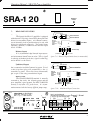
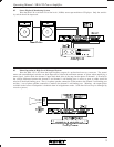
6.6 Headphone Jack
The Stereo headphone output jack will drive any
impedance stereo headphones. Channel 1 is connected
to the 1/4" jack tip contact and channel 2 is connected to
the ring.
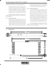
Ch.2 Out
p
120VAC
50-60Hz
350W
MDA 3A
TO REDUCE THE RISK OF ELECTRIC SHOCK DO NOT REMOVE
COVER. NO USER SERVICEABLE PARTS INSIDE. REFER
SERVICING TO QUALIFIED SERVICE PERSONNEL. TO REDUCE
THE RISK OF FIRE REPLACE ONLY WITH SAME TYPE FUSE.
TO REDUCE THE RISK OF FIRE OR ELECTRIC SHOCK DO NOT
EXPOSE THIS EQUIPMENT TO RAIN OR MOISTURE.
AVIS:
RISQUE DE CHOC ELECTRIQUE -
NE PAS OUVRIR.
SRA-120
Made In USA
6. FRONT PANEL FEATURES
6.1 Power Switch
When the unit is switched on there is a 2 second
delay, during which time the PROTECT circuit will acti-
vate. The load is disconnected during this power-up se-
quence . When turning off the amplifier, the load is re-
moved instantly, and the protect LED will briefly turn on
as the power supply discharges.
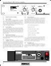
6.2 Level Controls
Front panel level controls allow precise indepen-
dent input level attenuation to the power amp sections.
When in mono or bridged mode, channel 1 controls both
power amp channels. We recommend setting these con-
trols full CW and controlling system gain at the mixer or
preamp instead.
6.3 Signal Present Indicators
Green signal present LED's indicate the presence
(about 30dB below maximum output) of signals into the
power amp circuitry.
6.4 Clipping Indicators
Clipping occurs when the signal peak levels ex-
tend beyond the available power supply rails, essentially
“cutting off” the crest portion of the waveform. This pro-
duces signal distortion and can potentially damage driv-
ers, as the signal begins to look like a square wave. The
red CLIP LED's illuminate at the onset of clipping, and
accurately track both the output load and the AC line volt-
age.