


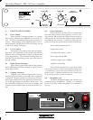
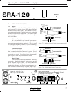

Operating Manual - SRA-120 Power Amplifier
4
1. INTRODUCTION
Congratulations on your purchase of the Ashly
SRA-120 professional stereo power amplifier. This single
rack-space (1 3/4" height) amplifier delivers a substan-
tial amount of power with exceptional audio quality and
many features typically found only in larger power am-
plifiers,
Both channels of the SRA-120 can easily drive 4
ohm loads, delivering a total of 120 watts of undistorted,
average sinewave power.
The amplifier has an automatic output turn-on
delay and instantaneous output turn-off to protect speak-
ers from transients. Each output will also turn off if it
"sees" a load of 2 ohms down to a short circuit. The out-
puts are also independently protected from overheat con-
ditions. Each channel will automatically reset itself from
any of these protection modes independent of the other
channel's operation.
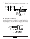
The SRA-120 provides front panel level controls,
a stereo headphone jack, and six status LED's for ease of
control and monitoring. The back panel provides both
balanced 1/4" jacks and balanced screw terminal inputs.
Three push-button switches allow selection of stereo,
mono, bridged mode, and input sensitivity, allowing the
amplifier to be applied in any configuration. The
amplifier's signal ground can also be lifted from chassis
ground via a barrier strip jumper.
2. UNPACKING
As a part of our system of quality control, every
Ashly product is carefully inspected before leaving the
factory to ensure flawless appearance. After unpacking,
please inspect for any physical damage. Save the ship-
ping carton and all packing materials, as they were care-
fully designed to reduce to minimum the possibility of
transportation damage should the unit again require pack-
ing and shipping. In the event that damage has occurred,
immediately notify your dealer so that a written claim to
cover the damages can be initiated.
The right to any claim against a public carrier
can be forfeited if the carrier is not notified promptly and
if the shipping carton and packing materials are not avail-
able for inspection by the carrier. Save all packing mate-
rials until the claim has been settled.
3. AC POWER REQUIREMENTS
3.1 Voltage Requirements
Your SRA-120 amplifier is supplied with a three
conductor grounded AC power cord, and should be
plugged into a standard 3-wire grounded electrical outlet
which supplies 120VAC 50-60 Hz (some export models
are wired for 100 or 240 volts and are labeled as such).
In the event of line voltage sag, or “brown-out”, SRA-
120 amplifiers will continue to operate normally, albeit
with less power.
3.2 Current Requirements
The actual AC current consumption by the am-
plifier depends greatly on the audio signal and the load
impedance. For typical audio program material with the
SRA-120 driving both channels just peaking at the clip-
ping level, the following AC line current is drawn and
should be used for system design purposes:
Idle 0.1A
8Ω loads 0.6 Amps
4Ω loads 1.0 Amps
Table 3.1: Estimated Maximum RMS AC Line Current
Draw
3.3 AC Grounding Requirements
To reduce the risk of ground loop hum, all sys-
tem ground references should originate at the same point
in your AC power distribution. Never remove the
amplifier’s ground pin as it is both unlawful and danger-
ous, creating a potential shock hazard.
4. CABLE REQUIREMENTS
4.1 Input Cables
Be sure to use shielded cable whether balanced
or unbalanced. Shielding which is properly grounded will
protect the signal from outside electrical interference such
as RF, fluorescent lighting, even computer noise. As a
general rule, unbalanced or single-ended (tip-sleeve) lines
of less than 10 feet are satisfactory, but greater distances
may require a balanced signal. Avoid running input lines
in close proximity or parallel to long speaker lines, AC
power cables, or power transformers, as this may gener-
ate hum or oscillation.