


5
Operating Manual - SRA-120 Power Amplifier
4.2 Output Cables
The wire gauge used for speaker cables is impor-
tant, in that inadequate wire gauge adds significant re-
sistance to the speaker’s own impedance, reducing the
power which is actually delivered to the speaker. It also
results in a decrease in the damping factor and possible
fire hazard.
Since power at the speaker load is a primary con-
cern in system design, we have included a table to best
determine appropriate wire gauge for your application.
Table 4.1 lists the percentage of the speaker load power
which would be lost in an arbitrary 100 ft. run of 2-con-
ductor cable. This table expresses the power loss as a
percentage of the load’s power rather than the total am-
plifier output power, so that you can use this table to ac-
curately determine power loss to the load at other cable
lengths. For example, if you plan to deliver 100 watts to
an 8Ω load through 50 ft of 14 ga. cable, the power loss
in the cable would be 3.2% ÷ 2 = 1.6% of 100 watts or
1.6 watts lost in the cable. Table 4.1 also gives the resis-
tance per 100 feet of common copper wire gauges.
Wire Gauge Ω/100ft 8Ω load 4Ω load 2Ω load
#8 .0605Ω 0.8% 1.5% 3.0%
#10 .1018Ω 1.3% 2.5% 5.1%
#12 .1619Ω 2.0% 4.0% 8.1%
#14 .2575Ω 3.2% 6.4% 12.9%
#16 .4094Ω 5.1% 10.2% 20.5%
#18 .6510Ω 8.1% 16.3% 32.6%
Table 4.1: Percentage of speaker load power lost in 100
foot run of 2-conductor cable.
5. RACK-MOUNTING REQUIREMENTS
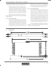
5.1 Mechanical
All Ashly amps are designed to fit in standard
19-inch racks. Avoid placing the amp immediately next
to devices which are sensitive to heat or magnetic fields
(high-gain preamps, magnetic data storage, etc.)
5.2 Cooling
The SRA-120 will cool more efficiently with
space above and below the chassis, although most appli-
cations will not require this.
The following chart indicates maximum BTU per
hour under varying load conditions, so that accurate as-
sessment of room ventilation needs can be made. Ther-
mal output is approximated by subtracting audio output
power from the total power consumption of the ampli-
fier. All values assume the amplifier is driving both chan-
nels and just peaking at the clipping level.
Idle 40 BTU
8Ω loads 200 BTU
4Ω loads 320 BTU
Table 5.2: Maximum BTU per hour (both channels driven)
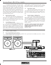
5.3 Grounding
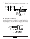
In some installations where a sound system is
sensitive to RF noise or system-induced oscillation, it may
be necessary to ground the amplifier's chassis to the rack
enclosure. This is accomplished using star type
lockwashers on the four rack mounting screws. These
star washers will penetrate through the amplifier's paint
to adequately ground the chassis to the rack.
5.4 Security Covers
For installations where it is desirable to protect
the front panel level controls from tampering or acciden-
tal misadjustment, use an Ashly security cover. Installa-
tion is simple and does not require removal of the equip-
ment from your rack. See your Ashly dealer for details.