


Operating Manual - PROTEA SYSTEM II Digital Audio Products
6
2. AC POWER REQUIREMENTS
Note: The AC power switch for model 4.24G is on the back panel. All Protea devices will perform nor-
mally from 90 to 125VAC. A standard IEC-320 AC inlet is provided on the rear panel to accept the detachable power
cord shipped with the unit. Units distributed within the United States are preselected for 115VAC, 50-60Hz and should
be plugged into a standard NEMA 5-15 3-wire grounded AC receptacle. Most units distributed outside the US are
preselected and labeled for 230VAC, 50-60Hz and are shipped with the appropriate power cord. In the event of fuse
failure, replace only with same type and rating fuse. If the fuse is internal, refer the product to a qualified service
technician for fuse replacement.
The 4.24RD remote control is phantom powered from its host through two standard three-conductor XLR cables.
3. UNPACKING
As a part of our system of quality control, every Ashly product is carefully inspected before leaving the factory
to ensure flawless appearance. After unpacking, please inspect for any physical damage. Save the shipping carton and
all packing materials, as they were carefully designed to reduce to minimum the possibility of transportation damage
should the unit again require packing and shipping. In the event that damage has occurred, immediately notify your
dealer so that a written claim to cover the damages can be initiated. The right to any claim against a public carrier can
be forfeited if the carrier is not notified promptly and if the shipping carton and packing materials are not available for
inspection by the carrier. Save all packing materials until the claim has been settled.
4. TYPICAL PROTEA APPLICATIONS
The Protea SYSTEM II product family includes five audio processors, a remote control, and Protea System
Software. Various Protea units can be combined to expand the capabilities of a system, adding channels, utilizing
remote control, or connecting to a PC. The following illustrations indicate some typical Protea systems.
See SYSTEM CONFIGURATION chart on p. 20 for specific switch and preference settings.
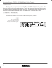
4.24RD Remote
XLR Data Out XLR Data In
XLR Data In
*4.24G Main
- Data Config Switch Out
Slaves
- Switch A Out, Switch B Out
Main Or Slave
XLR Data Out
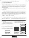
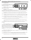
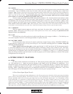
4.2 SINGLE UNIT WITH REMOTE CONTROL
The remote control unit (model 4.24RD) con-
nects to the main 4.24G or any other slave unit, and can
run up to 1000 ft. from the host audio unit.
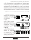
4.1 STAND-ALONE
Only the 4.24G can be used as a fully self-
contained processor, while any slave unit can func-
tion independently once it has been properly set up
through external hardware or software.
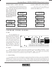
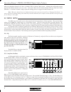
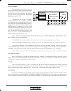
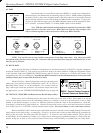
4.3 MULTI-CHANNEL PROTEA SYSTEM
Up to 16 different logical (MIDI) channels can
be simultaneously controlled from one Master in an ex-
panded Protea system.
XLR Data Out
XLR Data In
XLR Data In
4.24G Main
4.24RD Remote
XLR Data Out XLR Data In
XLR Data Out
XLR Data In
XLR Data Out
XLR Data In
XLR Data Out
XLR Data In
XLR Data Out
XLR Data In
*4.24G Main
- Data Config Switch Out
Slaves
- Switch A Out, Switch B Out
Main Or Slave
Main Or Slave
Main Or Slave
Main Or Slave
*4.24G Main
- Data Config Switch Out
Slaves
- Switch A Out, Switch B Out
*4.24G Main
- Data Config Switch Out
Slaves
- Switch A Out, Switch B Out
*4.24G Main
- Data Config Switch Out
Slaves
- Switch A Out, Switch B Out
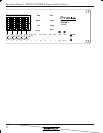
*4.24G Main
- UserPrefs LCD Menu Must Select MIDI
XLR Data Out
XLR Data In
XLR Data Out
XLR Data In
XLR Data Out
(
Data Config Switch Out)
Main Or Slave
Main Or Slave
Main Or Slave
*4.24G Main
- Data Config Switch Out
Slaves
- Switch A Out, Switch B Out
*4.24G Main
- Data Config Switch Out
Slaves
- Switch A Out, Switch B Out
*4.24G Main
- Data Config Switch Out
Slaves
- Switch A Out, Switch B Out
Select MASTER in UserPrefs