


Operating Manual - PROTEA SYSTEM II Digital Audio Products
14
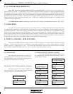
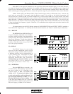
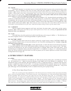
6.2 MIDI
Interconnection of several Protea units uses MIDI in a closed loop configuration,
where one unit is the Master and all remaining units are Slaves. MIDI channel assignment
for model 4.24G is done in the UserPref menu, while Slave units have front panel recessed
tactile switches adjacent to each LED readout for MIDI channel assignment. Using a pen-
cil point or other narrow object, press the MIDI Channel button until the appropriate chan-
nel is selected. Note that Channel "0" disables MIDI control of that channel.
Note: XLR data cables should be used throughout an expanded system when the 4.24RD
remote controller or any slave unit is used. MIDI cables are used only when multiple 4.24G
units are chained together or when connected to a third-party MIDI controller.
NOTE: It is crucial not to use any isolation transformers in the data connections. Also, when using XLR
microphone cables for data connections, pin 1 cannot be tied to ground anywhere along the transmission line, or the
unit may fail to function.
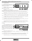
6.3 RS-232 DATA
Protea System Software for Windows communicates to the Protea hardware via RS-232, using the computer's
serial port (usually COM 1-4). The software can control 16 mono or 16 stereo channels. COM port assignment is done
in the software under the COMMUNICATIONS menu, and the Protea's connector is a D-Sub 9 pin female, fully
compatible with a PC serial COM port. Note that the RS232 connector can be switched instead to a six-scene recall
Contact Closure port on any of the Protea slave units.
Model 4.24G has a Data Configuration switch on the back panel,
while every slave unit has a Data Configuration switch "B", as well as a
Baud Rate Select Switch "A" on the back panel. For various switch set-
tings, cable types, baud rate selections, and software setups used in Pro-
tea applications, see the SYSTEM CONFIGURATION chart on page 20.
6.4 CONTACT CLOSURES and Remote Scene Recall (Slaves Only)
Protea slaves store individual presets and scenes the same way as the main 4.24G. Since there is no way to
access or alter these presets once the controlling hardware or software is removed, the need arises to use a small
number of pre-defined settings, or scenes, for different situations within the scope of the installation ie., room full,
room empty, volume at half, room divided, etc. Contact Closures offer an easy way to recall each of the first six Protea
slave scenes (see sec. 5.12 SCENE) with an external remote switch. PC control cannot co-exist with contact closures.
Remove the RS232 cable if used, then press the D-Sub connector's recessed switch to enable Contact Closure mode.
Scene change occurs upon closing, or connecting, a "hot pin" (see above chart) to the provided GND pin #5, presuming no
other hot pins are closed. The front panel LED will display "C X" where X is the scene number selected. The six pins can
be individually wired to momentary switches or to a rotary switch, allowing pre-programmed changes to a Protea slave unit.
Custom wiring may be used, or a six-position Contact Closure rotary switch assembly is available from your Ashly dealer.
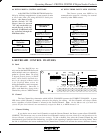
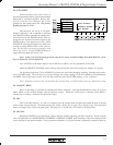
Pin # Function
1
2
3
4
5
NC
Out & Thru - Ground, In - NC
NC
Data +5V
Data Signal
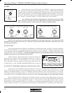
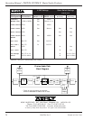
MIDI Pin-Out
13
4
2
5
13
4
2
5
PUSH
Data In XLR Data Out XLR
Pin # Function (Midi Pin #)
1
2
3
Phantom Ground
Data +5V
Data Signal
Pin # Function (Midi Pin #)
1
2
3
+24V Phantom Out
Data +5V
Data Signal
1
2
3
12
3
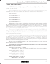
Protea 4.24G Main or Any Slave Data Connector Pin-Out
N/A
4
5
N/A
4
5
PUSH
Data In XLR Data Out XLR
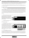
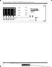
Pin # Function
1
2
3
+24V Phantom In
Data +5V
Data Signal From Host
Pin # Function
1
2
3
Phantom Ground
Data +5V
Data Signal to Host
1
2
3
1
2
3
4.24RD Remote Control Data Pin-Out
RS232
Contact
Closure
Pin# - Scene #
1 - 1
2 - 2
3 - 3
4 - 4
6 - 5
7 - 6
Pin 5 = GND
1
2345
9876
RS232/Contact Closure Connector
(Contact Closure on Slaves Only)