


9
Operating Manual - NE Two Channel Power Amplifiers
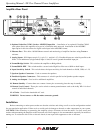
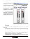
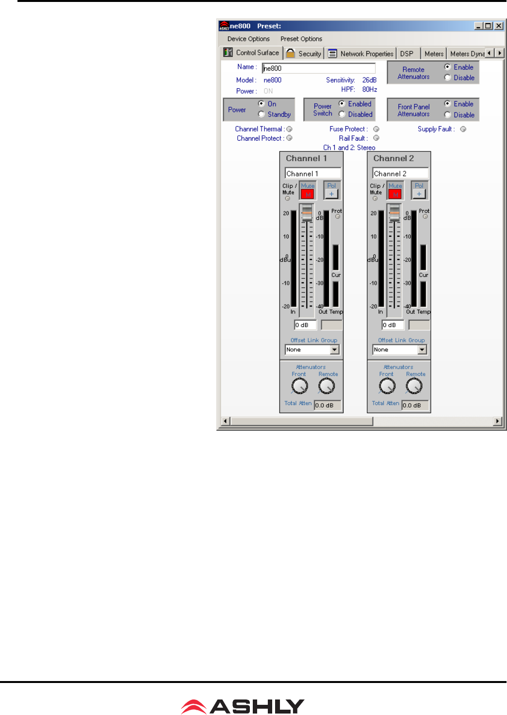
5) Attenuators - These two dials indi-
cate the physical position of hardware controls
on either the amp front panel or the remote
level control (if present). Note that these will
display the position of attenuators even when
DISABLED in software.
6) Total Attenuation - This indicates the
total amount of attenuation being applied to
the channel. This is the sum of the fol-
lowing attenuators: main fader, offset link
group attenuation, front panel and remote at-
tenuators (if enabled).
7) Meters - Input and Output meters dis-
play the real time activity per channel, in dB
below rated output. Also, the amplifier’s op-
erating temperature and output current are
shown. Output current shows that the ampli-
fier channel is actually delivering output to a
connected speaker load.
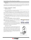
Protea
ne
Two-Channel Amplifier Control Surface
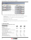
The DSP Window
Extensive online help information is available for all DSP blocks. Look in the Protea
ne
Software Help Menu/
Contents and Index/Contents/Protea NE Products/NE Amplifiers/DSP Control for details of all DSP functions. The key
features include:
1) Input Channel Number - Right click on this to bring up Clear, Copy, Link, and Sub Preset functions for that
input channel.
2) Input Channel Name - The user can name each input channel.
3) Input Mute Button - Mutes the input.
4) Pluggable Input DSP Tools - Six boxes are available for custom configuration of pluggable DSP processing
blocks. Available DSP blocks include Dynamics controls, Gain and Remote Gain functions, Graphic and
Parametric EQ, Crossover functions, Delay, Metering, and a Signal Generator.
5) Input/Output Matrix Router - Any input can be routed to any or all outputs. Click and drag from the input to
output to assign routing. To delete a route, right click on the routing line and delete.