


7
Operating Manual - NE Two Channel Power Amplifiers
Requirements
Ashly NE two channel amplifiers have specific physical, electrical and signal requirements for proper operation.
These requirements will vary depending on your specific application, setup, and the settings on the amplifier. When
setting up and testing your system, please take special care to double check all connections and settings. Please refer to
the specifications section of this manual for specific input, output and other figures.
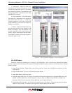
4. REMOTE AMPLIFIER CONTROL
ON/OFF/Remote Standby
The NE two channel amplifiers have three possible states, OFF, ON, and STANDBY, each with a status LED on the
front panel. Control for these three states is managed by the following:
1) Power Switch - When the power switch is turned off the amplifier is completely off, UNLESS the power switch
has been disabled from within Protea
ne
software, in which case the power switch on the amplifier has no effect at all. If
the power switch has been disabled from software, the front panel DISABLE LED will be lit. Even if the AC power is
removed, the amplifier’s internal memory will maintain the <power switch disabled> status until changed again from
Protea
ne
software. Performing a factory reset will clear and restore all internal amplifier memory to factory settings.
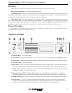
2) Remote Standby Contact Closure - When these two euroblock pins on the back of the amplifier (see amplifier
rear panel illustration #10) are wired to a switch and connected, the amp will go into Standby mode, whereby the amp is
active but not fully powered up. For Remote Standby to work, the power switch must be turned on OR be disabled
through Protea
ne
software.
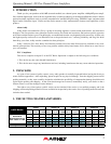
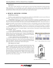
3) Protea
ne
Software On/Standby - On/Standby in the Protea
ne
two
channel amp software functions the same as the hardware based Remote
Standby Contact Closure on the back panel. Clicking on STANDBY places
the amp in standby mode. The On/Standby in software does not override the
hardware Remote Standby, they both remain active.
4) Protea
ne
Software Power Switch Enable/Disable - Use this soft-
ware feature to disallow use of the front panel power switch. If the power
switch has been disabled from software, the front panel DISABLE LED will
light on the amplifier. The power switch will remain inactive until enabled
again from software, even if the amp is removed from power.
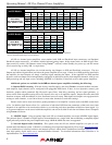
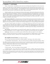
WR-1 Remote Level Control
Either amplifier channel can have remote attenuation by using a poten-
tiometer assembly such as the Ashly WR-1 and four conductor wire. The
WR-1 is a dual potentiometer remote volume control designed to fit in a
standard electrical wall box. Each volume control is connected to a terminal
block on the WR-1 circuit board, which in turn must be wired to the amplifier
back panel euroblock connector labeled "Remote Level Control" as shown.
CV-1 = Control Voltage for Channel 1, etc. There is no wire length limitation
for Remote Level Control. Do not connect the WR-1 remote level control
ground to any other external grounds.
Protea
ne
Software Remote Power Control
G
CV-2
+5
G
CV-1
+5
Ashly WR-1 Remote Level Control