


9
Operating Manual - FTX-1001, FTX-1501, FTX-2001, CFT-1800 Power Amplifier
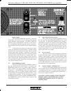
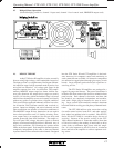
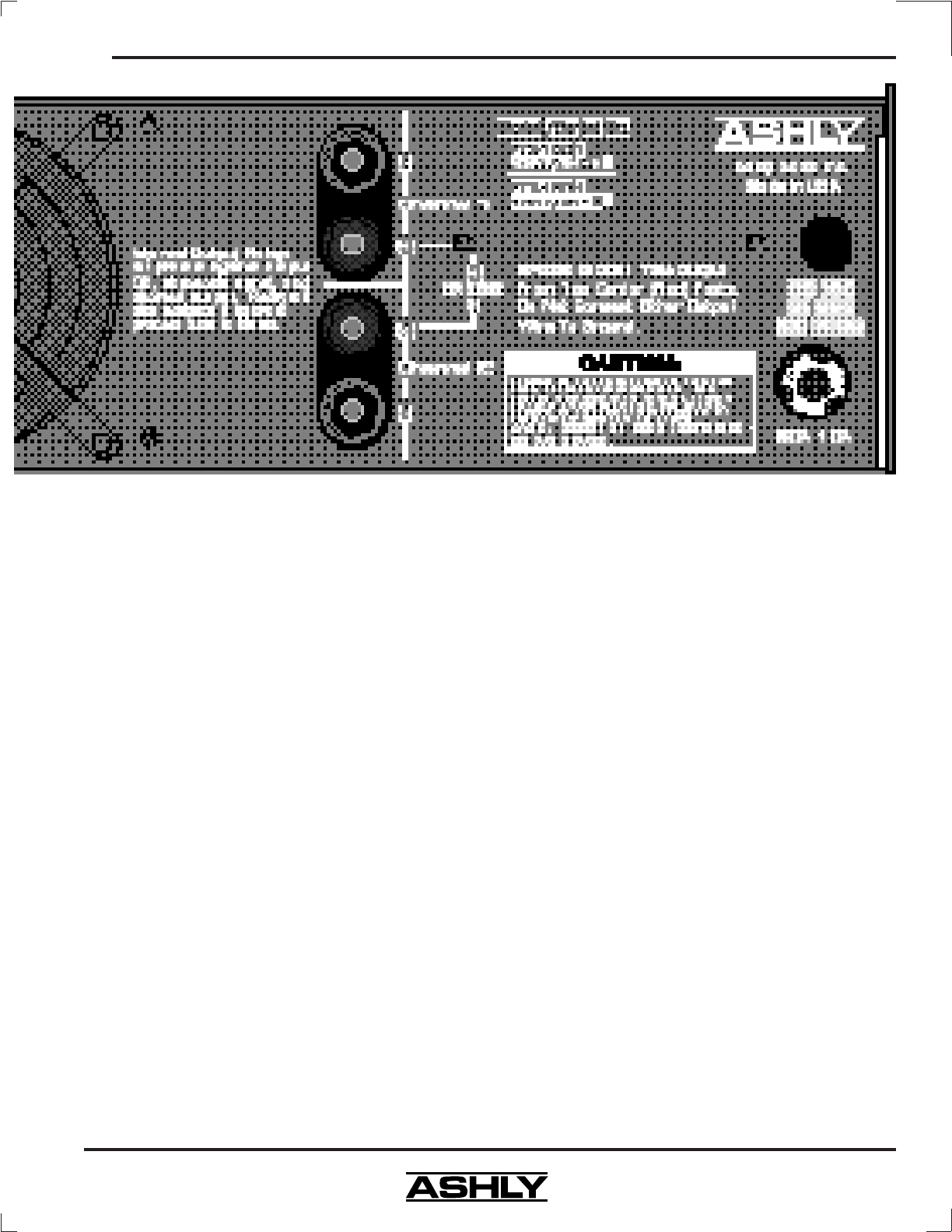
Input Ground
The CHASSIS GROUND terminal is internally
connected to the chassis, the AC earth ground, and the
power amplifier’s signal ground. The INPUT GROUND
terminal is tied to the XLR pin 1 and the 1/4" jack sleeve.
It is recommended that the input and chassis ground ter-
minals remain connected with the factory-supplied jumper
strap.
In situations where the power amp and its signal
source are separated by great distances, a ground voltage
difference may exist between the amp’s chassis ground
and the input cable’s ground. Connection of these two
grounds through the jumper strap may cause large ground
currents to flow (which is known as a ground loop), caus-
ing a hum noise in the amp’s output. Unless you have
such a situation with a hum problem that cannot be solved
by using balanced input connections, the ground jumper
strap should remain in place.
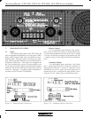
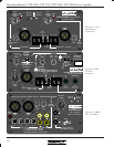
7.2 Normal/Bridging Switch
This switch selects between NORMAL mode in
the “out” position where both channels are in-phase, and
BRIDGING mode in the “in” position where channel 1
input is used to drive both channels, inverting the phase
of channel 2. In BRIDGING mode, the channel 1 red
binding post is the (+) in- phase speaker output terminal
and the channel 2 red binding post becomes the (-) out-
of-phase speaker terminal. It is not necessary to depress
the MONO switch in order to operate in BRIDGED mode.
The BRIDGING switch overrides either setting of the
Stereo/Mono Switch.
7.3 Stereo/Parallel Mono Switch
This switch selects between STEREO mode in
the “out” position and PARALLEL MONO mode in the
“in” position. In PARALLEL MONO mode, channel 1
and channel 2 inputs are internally tied together before
the input attenuator, allowing discrete channel control of
a mono signal. CAUTION: Be sure not to have two sig-
nal sources connected to ch.1 and ch.2 inputs when in
parallel mono mode, as it would short-circuit these two
signals and result in no output.
7.4 Level Controls
The level controls allow attenuation (calibrated
in dB) of the input signal. In PARALLEL MONO mode,
channel 1 and channel 2 inputs are tied together, while
still preserving independent level control per channel. In
BRIDGED mode, use only channel 1 level control. It is
recommended that the level controls be operated at full
level (0 dB attenuation) in most situations to maximize
the headroom in the signal source.
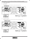
7.5 Speaker Outputs - Binding Posts
A pair of dual banana binding posts provide the
stereo speaker outputs. In BRIDGING mode, the channel
1 red binding post is the (+) in-phase speaker output ter-
minal and the channel 2 red binding post becomes the (-)
out-of-phase speaker terminal.
CAUTION! NEVER CONNECT THE TWO RED
BINDING POSTS TOGETHER OR CONNECT
EITHER RED BINDING POST TO A BLACK
BINDING POST!