


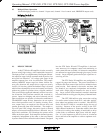

Operating Manual - FTX-1001, FTX-1501, FTX-2001, CFT-1800 Power Amplifier
4
1. INTRODUCTION
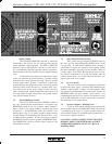
The Ashly FTX Series III MOSFET amplifiers
combine the sonic excellence of a high-end stereo amp
with the ruggedness and stamina necessary in pro audio.
The FTX Series III amps use lateral power MOSFETs
(metal-oxide-semiconductor, field-effect transistors) for
their superior audio fidelity and unmatched reliability as
proven in Ashly amps for over fifteen years. These
MOSFET output devices exhibit many superior perfor-
mance characteristics over the conventional bipolar power
transistors used in most conventional power amp designs.
They are inherently self-regulating and do not exhibit
many of the failure modes of bipolar transistors.
MOSFETS have no thermal runaway tendency so
the need for temperature tracking bias circuitry is elimi-
nated, making the design simpler and more reliable.
MOSFETS do not suffer from secondary break-
down (the primary failure mechanism in in bipolar tran-
sistors which requires complex dissipation limiting to
avoid.) The MOSFET will even withstand a shorted load
and self-limit the resulting high drain current without any
protection circuitry for a short time.
MOSFETS do not have a “minority carrier stor-
age time” (a phenomenon found in bipolar transistors in
which a certain amount of time is required to turn the
transistor off). Therefore the MOSFET is said to be a
“fast” device which can function very accurately and ef-
ficiently with high amplitude/high frequency signals and
transient waveforms.
The FTX series III amplifiers are the result of
years of refinement to the original Ashly MOSFET de-
sign. The current circuit is cleaner, quieter, and more
stable than ever before. A number of improvements have
been made in the area of thermal management using new
insulating materials and increased heatsink area, allow-
ing even more robust performance into difficult loads.
Protective systems have been refined to add even more
insurance against gross faults such as short circuits and
the application of speaker damaging signals to the ampli-
fier. The module assembly is produced using assembly
techniques including individual testing of each compo-
nent before it is placed on the PC board, and a state-of-
the-art soldering system which insures excellent strength
and ruggedness.
The FTX series III uses the latest generation of
lateral MOSFETS. These components also improve on a
time honored design. The result is higher bandwidth,
improved power handling, and better matching. The all-
metal case of these transistors results in a ruggedness not
possible with plastic designs.
The unmatched reliability of the power MOSFET
output devices, the clever mechanical design, and the
careful assembly techniques of the FTX Series III ampli-
fiers ensure years of maintenance-free service.
2. UNPACKING
As a part of our system of quality control, every
Ashly product is carefully inspected before leaving the
factory to ensure flawless appearance. After unpacking,
please inspect for any physical damage. Save the ship-
ping carton and all packing materials, as they were care-
fully designed to reduce to minimum the possibility of
transportation damage should the unit again require pack-
ing and shipping. In the event that damage has occurred,
immediately notify your dealer so that a written claim to
cover the damages can be initiated.
The right to any claim against a public carrier
can be forfeited if the carrier is not notified promptly and
if the shipping carton and packing materials are not avail-
able for inspection by the carrier. Save all packing mate-
rials until the claim has been settled.
3. AC POWER REQUIREMENTS
3.1 Voltage Requirements
Your FTX Series III amplifier is supplied with a
three conductor grounded AC power cord, and should be
plugged into a standard 3-wire grounded electrical outlet
which supplies 120VAC 50-60 Hz (some export models
are wired for 100 or 240 volts and are labeled as such).
In the event of line voltage sag, or “brown-out”, FTX
Series III amplifiers will continue to operate normally,
albeit with less power.
3.2 Current Requirements
A 15 amp circuit is sufficient for normal opera-
tion down to 2Ω loads. The actual AC current consump-
tion by the amplifier depends greatly on the audio signal
and the load impedance. For typical audio program ma-
terial with the amplifier driving both channels just peak-
ing at the clipping level, the following AC line current
capacities are recommended for system design purposes: