


5
Operating Manual - FTX-1001, FTX-1501, FTX-2001, CFT-1800 Power Amplifier
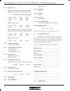
FTX-1001 FTX-1501 FTX-2001
Idle .5A .6A 1.5A
8Ω loads 2 Amps 2.5 Amps 3.5 Amps
4Ω loads 3 Amps 4 Amps 6 Amps
2Ω loads --- 7 Amps 10 Amps
Table 3.1: Recommended AC line current capacity
All FTX Series III amplifiers consume less than
12 amps when operating at 1/8 power into 2Ω loads. This
condition satisfies the UL, CSA and building electrical
code requirements for a piece of audio equipment not to
consume more than 80% of the current available when
plugged into a grounded 15 amp outlet and operated
at 1/
8 of maximum power.
3.3 AC Grounding Requirements
To reduce the risk of ground loop hum, all sys-
tem ground references should originate at the same point
in your AC power distribution. Never remove the
amplifier’s ground pin as it is both unlawful and danger-
ous, creating a potential shock hazard.
4. CABLE REQUIREMENTS
4.1 Input Cables
Be sure to use shielded cable whether balanced
or unbalanced. Shielding which is properly grounded will
protect the signal from outside electrical interference such
as RF, fluorescent lighting, even computer noise. As a
general rule, unbalanced or single-ended (tip-sleeve) lines
of less than 10 feet are satisfactory, but greater distances
may require a balanced signal. Avoid running input lines
in close proximity or parallel to long speaker lines, AC
power cables, or power transformers, as this may gener-
ate hum or oscillation.
4.2 Output Cables
The FTX Series III amplifiers are capable of de-
livering high levels of output current, therefore the wire
gauge used for speaker cables is particularly important.
Inadequate wire gauge adds significant resistance to the
speaker’s own impedance, reducing the power which is
actually delivered to the speaker. It will also result in a
decrease in the damping factor and possible fire hazard.
Since power at the speaker load is a primary con-
cern in system design, we have included a table to best
determine appropriate wire gauge for your application.
Table 4.1 lists the percentage of the speaker load power
which would be lost in an arbitrary 100 ft run of 2-con-
ductor cable. This table expresses the power loss as a
percentage of the load’s power rather than the total am-
plifier output power, so that you can use this table to ac-
curately determine power loss to the load at other cable
lengths. For example, if you plan to deliver 100 watts to
an 8Ω load through 50 ft of 14 ga. cable, the power loss
in the cable would be 3.2% ÷ 2 = 1.6% of 100 watts or
1.6 watts lost in the cable. Table 4.1 also gives the resis-
tance per 100 feet of common copper wire gauges.
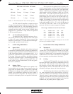
Wire Gauge Ω/100ft 8Ω load 4Ω load 2Ω load
#8 .0605Ω 0.8% 1.5% 3.0%
#10 .1018Ω 1.3% 2.5% 5.1%
#12 .1619Ω 2.0% 4.0% 8.1%
#14 .2575Ω 3.2% 6.4% 12.9%
#16 .4094Ω 5.1% 10.2% 20.5%
#18 .6510Ω 8.1% 16.3% 32.6%
Table 4.1: Percentage of speaker load power lost in 100
foot run of 2-conductor cable.
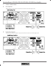
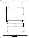
5. RACK-MOUNTING REQUIREMENTS
5.1 Mechanical
All Ashly amps are designed to fit in standard
19-inch racks. The front panel rack-mount ears are suffi-
ciently strong for most applications. If you desire further
integrity for mobile racks, we recommend using the four
additional holes in the back of the chassis for supplemen-
tal rear-mounting (see dimensional drawings).
5.2 Cooling
If using an FTX amplifier, be certain that both
the front and back of the rack have unhindered access to
free air flow. Fan direction is from front to back. It is
not necessary to leave empty space above or below the
FTX amplifiers, however the CFT-1800 will cool more
efficiently with space above and below the chassis.
The following chart indicates max BTU per hour
for each amp under varying load conditions, so that ac-
curate assessment of room ventilation needs can be made.
Thermal output is approximated by subtracting audio
output power from the total power consumption of the
amplifier. All values assume the amplifier is driving both
channels and just peaking at the clipping level.