


Operating Manual - PROTEA SYSTEM II 4.24C Crossover / System Processor
8
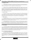
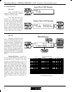
of the venue with direct line-of-sound to multiple loudspeakers. The solution is to
delay the audio signal to the loudspeakers located beyond the main stage area, so that
sound comes out of the distant loudspeakers at the exact time that sound from the
main stage loudspeakers arrives. Within the Protea 4.24C, up to 682 milliseconds of
time delay are available on each input channel, allowing secondary loudspeaker
clusters to be time aligned with the primary speakers up to 771 feet (235m) away
from the main stage area.
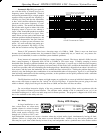
Output channels have time delay as
well, but much less than the inputs. This is
because output delay is best used to align dis-
crete drivers within a speaker cabinet or clus-
ter, normally quite close together. For example,
a typical three way speaker cluster would have
low end, midrange, and high frequency drivers
all located near one another. The different driv-
ers for each frequency band are not necessar-
ily the same physical depth with respect to the
front of the loudspeaker cluster, so there ex-
ists the problem of same signals (at the cross-
over points) arriving at the cluster "front" at
different times, creating undesirable wave in-
teraction and frequency cancellation. The so-
lution, again, is to slightly delay the signal to
the drivers closest to the cluster front. Using
the location of the driver diaphragm farthest
back as a reference point, measure the distance to other drivers in the cluster, and set
the output delay for each accordingly, with the driver diaphragm closest to the front
getting the longest delay and the driver at the very back getting no output delay.
Note: Although delay in the 4.24C is adjusted only by time, the corresponding dis-
tance in both feet and meters is always shown as well.
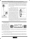
4.6d Crossover (Xover)
Crossover functions on the
Protea 4.24C are available only on the
eight output channels. Every
channel's crossover consists of a high
pass filter (HPF) and a low pass filter
(LPF), along with the frequencies and
filter types used. Each output's cross-
over section is essentially a bandpass
filter, making it necessary for the user
to map out ahead of time which outputs will be used for the various frequency bands, and set the overlapping filter
frequencies and types accordingly. Note: The HPF determines the lower frequendy limit of the signal, while the LPF
determines the upper frequency limit.
The frequency range for the high pass filter (HPF) is from 19.7Hz to 21.9kHz, with an option to turn the filter
off at the low end of the frequency selection. The low pass filter (LPF) offers the same frequency range, with the "off"
option at the high end of the frequency selection.
There are eleven types of filters available in the crossover section, each suited to a specific preference or
purpose. The slope of each filter type is defined by the first characters in the filter type, 12dB, 18dB, 24dB, or 48dB
per octave. The steeper the slope, the more abruptly the "edges" of the pass band will drop off. There is no best filter
Same sound arrives at
two different times.
Fix b
y
dela
y
in
g
secondar
y
speakers 177mS.
Speaker on
Main Sta
g
e
Secondar
y
Speaker
200 ft from Main Sta
g
e
Input (Lon
g
) Time Dela
y
For Remote Speakers
Hi
g
h - No Dela
y
Midran
g
e Dela
y
12 Inches = 0.9mS
Low Dela
y
8 Inches = 0.6mS
Example: 12 Inches
Example: 8 Inches
Out
p
ut
(
Short
)
Time Dela
y
For Driver Ali
g
nment
Crossover
Channel 1-8
HPF or LPF
Frequency
Crossover LCD Displa
y
Select
Slo
p
e and
Res
p
onse
HPF and LPF
CROSSOVER 1
19.7Hz
HPF
24dB-Lnkwtz