


5
Operating Manual - PROTEA SYSTEM II 4.24C Crossover / System Processor
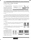
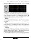
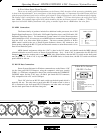
4. FRONT PANEL CONTROL FEATURES
4.1 Function Keys and Data Wheel
To the right of the LCD display
are two unlabeled function keys and a
rotary data wheel. All audio and sys-
tem parameters are edited using these
three controls. Each of the two lines of
text on the LCD display correspond to
a dedicated function key, so that vari-
ous tasks on both lines may be selected
using their respective keys. The selected task is highlighted by a flashing underscore beneath the word or number, and
the parameter is then adjusted up or down with the data wheel. The Esc key will exit any activity and return to the top
level showing the preset number and name.
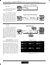
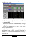
4.2 Presets
The 4.24C is organized into 30 programmable presets, each completely defining the configuration of all four
inputs and eight outputs along with their respective audio components. There are ten repeating preset configurations
pre-loaded into the 4.24C which are simply starting points for common applications, and all can be modified, re-
named, and saved to suit the end user. Please Note: In addition to the 30 preset numbers, a constantly refreshed
Working Preset is used to take a "snapshot" of all current settings should the unit be turned off before changes can be
saved.
When the 4.24C is first powered up, the last working preset is loaded, displaying the number and name last
used before the unit was turned off. Any modifications made to that preset before saving it will remain in the working
preset until either the modified preset is saved, or a fresh preset is recalled to the 4.24C. When modifications to an
existing preset are made without saving, the display adds the text modifiedafter the preset number.
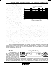
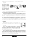
4.3 Input Select
There are four audio inputs to the 4.24C, and each input is processed indepen-
dently and may be routed to one or several outputs. Select an input to edit its Gain, EQ,
and Delay settings, or to mute it. Signal routing occurs in the output section.
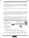
4.4 Output Select
There are eight outputs to the 4.24C, and each output can obtain its source from
any input, several combinations of inputs, or no input (off). Select an output channel to
edit its Source, Gain, Polarity, EQ, Delay, Crossover, or Limiter functions.
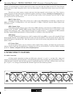
4.5 LED Indicators
Each input and output has a
five segment LED array for audio level
display, ranging from -20 through clip-
ping. The -20 LED is two-color, also
serving as the Mute indicator by turn-
ing red. The meter scale is factory set
so that 0 on the meter is 0dBu
(0.775Vrms), however it can be eas-
ily changed to VU scale (0 = +4dBu,
or 1.228Vrms) within the Util menu.
Preset 01
4 x 2-way Crossover
Esc
24 Bit Di
g
ital Crossover S
y
stem Processor
-20/
Mute
-10
0
+1 0
Clip
ABCD
Input Select
-20/
Mute
-10
0
Lim
Clip
Output Select
12345678
EQ
Xover
Limit
Dela
y
Gain
Save
Cop
y
Mute
Recall
Util