


13
Operating Manual - PROTEA SYSTEM II 4.24C Crossover / System Processor
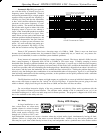
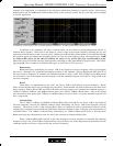
A Note About Input Signal Levels:
There are no analog gain trim adjustments on the Protea 4.24C, therefore all the processing (including gain)
is done in the digital domain. As a consequence of this design philosophy, it is important to feed the Protea processor
with the proper nominal signal level to achieve good signal to noise performance as well as headroom before clipping.
The Protea 4.24C is designed to clip at signal levels above +20dBu = 7.75Vrms which places the noise floor lower
than -90dBu. The optimum input signal level which should be fed into the Protea processor is 0dBu = .775Vrms. This
input level will allow 20dB of headroom while giving a nominal signal that is >90dB above the noise floor.
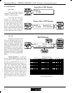
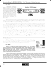
5.2 MIDI Connections
The Protea family of products include five additional audio processors, the 4.24G
Graphic Equalizer/Processor, 2.24S and 4.24S Graphic Equalizer slaves, and 2.24P and 4.24P
Parametric Equalizer Slaves. For simultaneous system control of several Protea products
which include the 4.24C, it is necessary to use MIDI cables to communicate program changes
from the 4.24C to or from other Protea products. The most common instance of Protea
MIDI control would be the use of Protea System Software, where a PC connects to one
Protea product (through the RS-232 jack) and that unit connects to other Protea units via its
Data In and Data Out jacks.
MIDI channel assignment within the 4.24C is done in the Util menu, and should match the MIDI channel
selected within the crossover section of Protea System Software. Note: If the 4.24C is connected to the PC (RS-232
Dataport)
and looped to another unit(s) via both MIDI jacks (Data In/Out), then the RS-232 switch on the back panel
must be pushed in. If the 4.24C is any other part of the MIDI chain, or stands alone, the RS-232 switch on the back
panel should be left out.
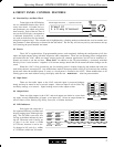
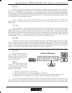
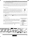
5.3 RS-232 Data Connections
Protea System Software for Windows communicates to the Protea 4.24C
via the front panel RS-232 Dataport, using the computer's serial port (usually
COM 1-4). COM port assignment is done in the software under the COMMUNI-
CATIONS menu, and the 4.24C uses a D-Sub 9 pin female RS-232 connector,
fully compatible with a PC serial COM port.
The 4.24C also has an RS-232 mode switch on the back panel which is
normally left out. The only time to push in the RS-232 mode switch is when a
PC is connected to the front panel RS-232 Dataport, and other units are looped
into the back panel Data In and Data Out jacks.
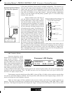
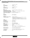
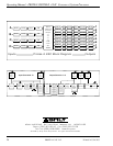
D-Sub 9 Pin Female
RS-232 Pin-Out
12345
9876
Pin # RS-232 DCE Name
1
2
3
4
5
6
7
8
9
Not Connected
Transmitted Data
Received Data
Data Terminal Read
y
(tied to pin 6)
Ground
Data Set Read
y
(tied to pin 4)
Not Connected
Not Connected
Not Connected
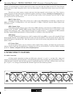
5678
Data Out
Standard Mode
Multiple Slave Mode
(1st Unit Only)
Ashl
y
Audio Inc.
Made In USA
4.24C
80-240VAC 50-60Hz 20W
On
AC
RS-232
Di
g
ital Audio Products
1/4A Max
Risk of Electric
Shock. Do
Not Open
CAUTION
Data In
Pin # Function
1
2
3
4
5
NC
Out & Thru - Ground, In - NC
NC
Data +5V
Data Si
g
nal
MIDI Pin-Out
13
4
2
5