


3
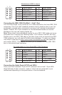
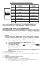
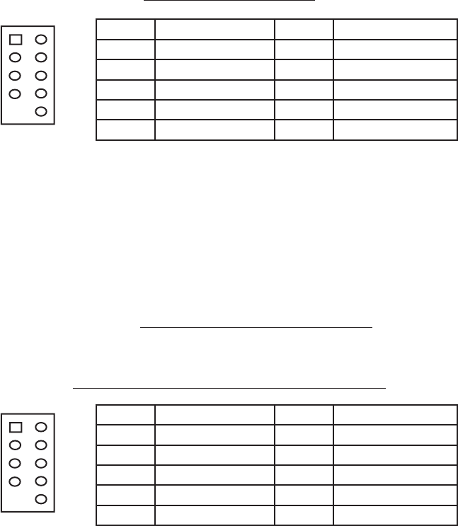
Motherboard USB Pin Layout
Pin Signal Names Pin Signal Names
1
USB Power 1
2
USB Power 2
3
Negative Signal 1
4
Negative Signal 2
5
Positive Signal 1
6
Positive Signal 2
7
Ground 1
8
Ground 2
9
Key (No Connection)
10
Empty Pin
12
109
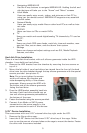
Connecting the IEEE 1394 (FireWire®, i.Link®) Port
You will find a single 10-pin connector on a cable attached to the front IEEE 1394
connection. This is an Intel® standard connector that is keyed so that it can’t be
accidentally reversed when connected to a proper Intel® standard motherboard
header. Connect the 10-pin connector to the motherboard header so that the
blocked pin fits over the missing header pin.
Note: Please check the motherboard manual for your IEEE 1394 header pin layout
and make sure it matches the following table. If you intend to connect the front
FireWire port to an IEEE 1394 add-on card that comes with an external-type IEEE
1394 connector, you will need a FireWire Internal Adapter. To order one, please
visit Antec’s web store at http://www.antec.com/StoreFront.bok and search for
part number 30031. This adapter will allow you to connect the front IEEE 1394
port to the external-type connector.
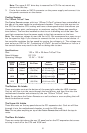
Pin Assignment for Front Panel IEEE 1394 Connector
Pin Signal Names Pin Signal Names
1 TPA+ 2 TPA–
3 Ground 4 Ground
5 TPB+ 6 TPB–
7 +12V (Fused) 8 +12V (Fused)
9 Key (No Pin) 10 Ground
12
109
Connecting the Audio Ports (AC’97 and HDA)
There is an Intel® standard 10-pin AC’97 connector and an Intel® 10-pin HDA
(High Definition Audio) connector, either of which can be connected to your
motherboard depending on the specification of the motherboard.