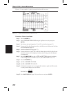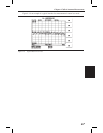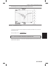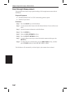
Step 10. Press the MEAS key to initiate actual measurement. The Site Master will display
the measurement results in the display area.
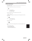
The Site Master default value for the % method is 99%, and N dBc down is 3 dB
down.
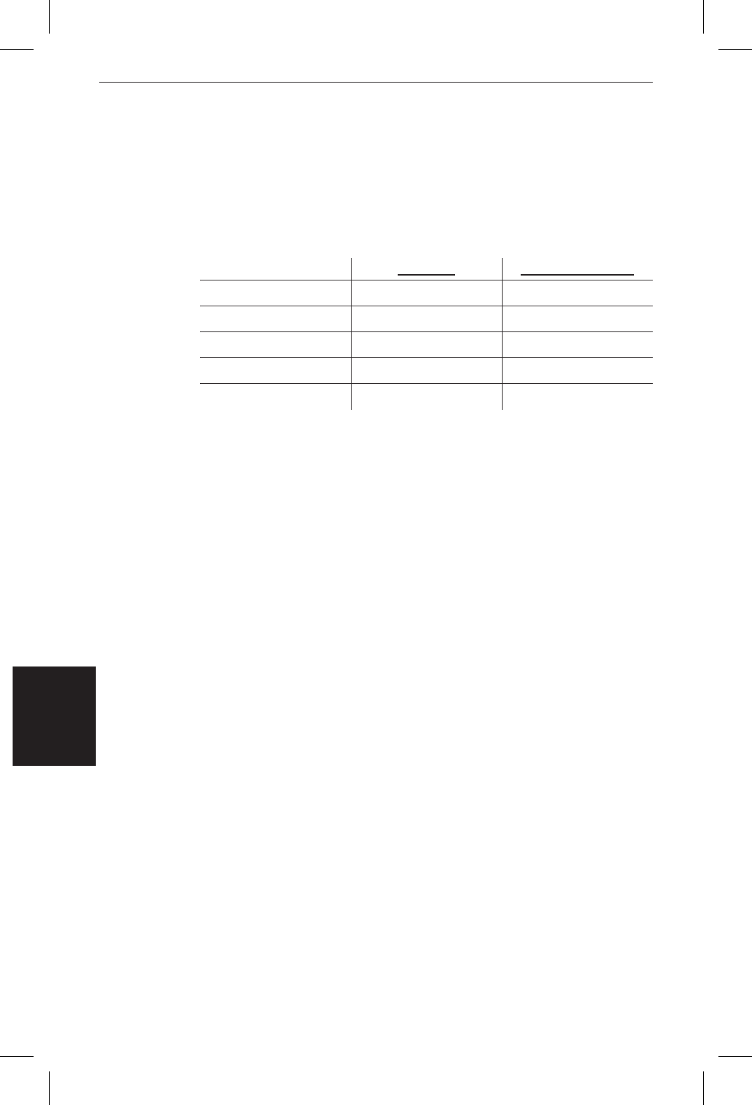
The table below provides typical instrument settings for measuring a CW and an
IS-95 CDMA signal.
Channel Power Measurement
One of the most common measurements for a transmitter is that of channel power. This test
measures the output power, or channel power, of a transmitter over a frequency range and a
specific time interval. Channel Power measurements are used to validate transmitter perfor-
mance, verify compliance with FCC regulations, and keep overall system interference at a
minimum.
Out-of-specification power measurements indicate system faults in the power amplifier or
in-filter circuits.
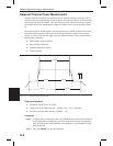
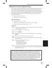
Channel Power Measurement with the Site Master
The Site Master can be used to measure CDMA signals in terms of channel power. It is nec
-
essary to use precise and specific settings to accurately measure the CDMA signal because
the CDMA is different from CW signals.
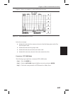
For accurate IS-95 CDMA measurements, use the following settings:
q
CDMA Channel Bandwidth: 1.23 MHz
q
RBW setting: 10 kHz
q
VBW ³ 3´ RBW or at least 30 kHz
q
Averaging function turned off
Required Equipment
q
Site Master Model S114C or S332C
q
30 dB, 50 Watt, bi-directional, DC –18 GHz, N(m) – N(f), Attenuator
q
Test Port extension cable, Anritsu 15NNF50 – 1.5C
5-2
Chapter 5 Spectrum Analyzer Measurements
CW Wave IS-95 CDMA Signal
Frequency Span 900 MHz 900 MHz
Reference Level –15 dBm –10 dBm
Input Attenuation Level Auto Auto
Resolution Bandwidth Auto 10 kHz
Video Bandwidth Auto 30 kHz
Table 5-1. Typical Occupied Bandwidth Measurement Settings


