


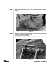
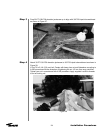
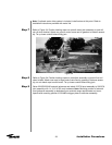

Step 7
Step 8
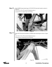
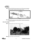
Step 9
28
Installation Procedures
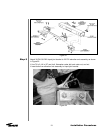
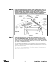
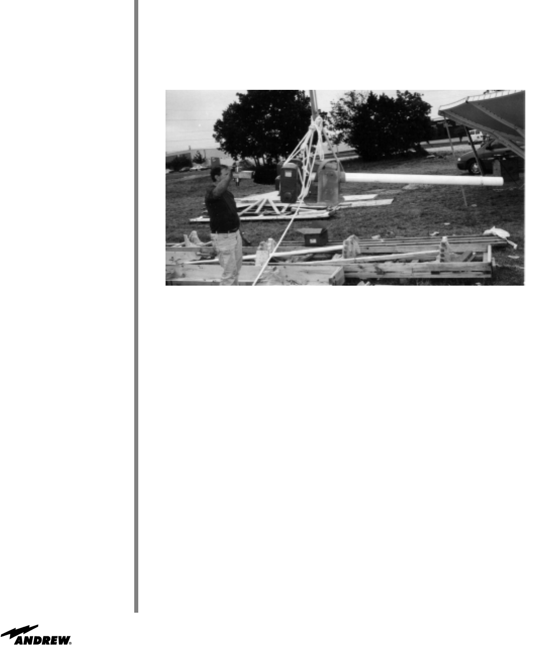
Figure 34
Refer to Figure 34. Position hoisting ropes on motor/jack assembly so jack will not roll
when hoisted. Attach one rope to large motor frame next to gearbox to balance assem-
bly; do not attach rope to small motor. Tie up loose conduit before lifting jack.
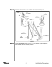
Raise 221923/223180 azimuth jackscrew and attach 221738 pivot assembly to 201327A
joint assembly with 1 x 2-1/2 in (63 mm) hardware. Note: Mounting position of azimuth
pivot jackscrew assembly is dependent upon azimuth range requirements and corre-
sponds with mounting position of 201488 outrigger plate or extension assembly.
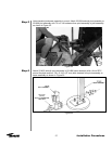
Note: If optional motor drive system is included, install motors at this point. Refer to
installation instructions provided with motor kits.
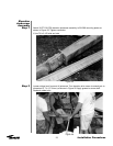
Refer to Figure 34. Position hoisting ropes on azimuth motor jack assembly so jack will
not roll when hoisted. Attach one rope to motor frame next to gearbox to balance assem-
bly. Tie up loose conduit before lifting jack.