


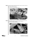
Step 5
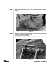
Step 6
15
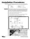
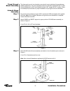
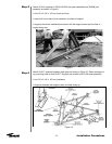
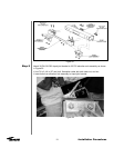
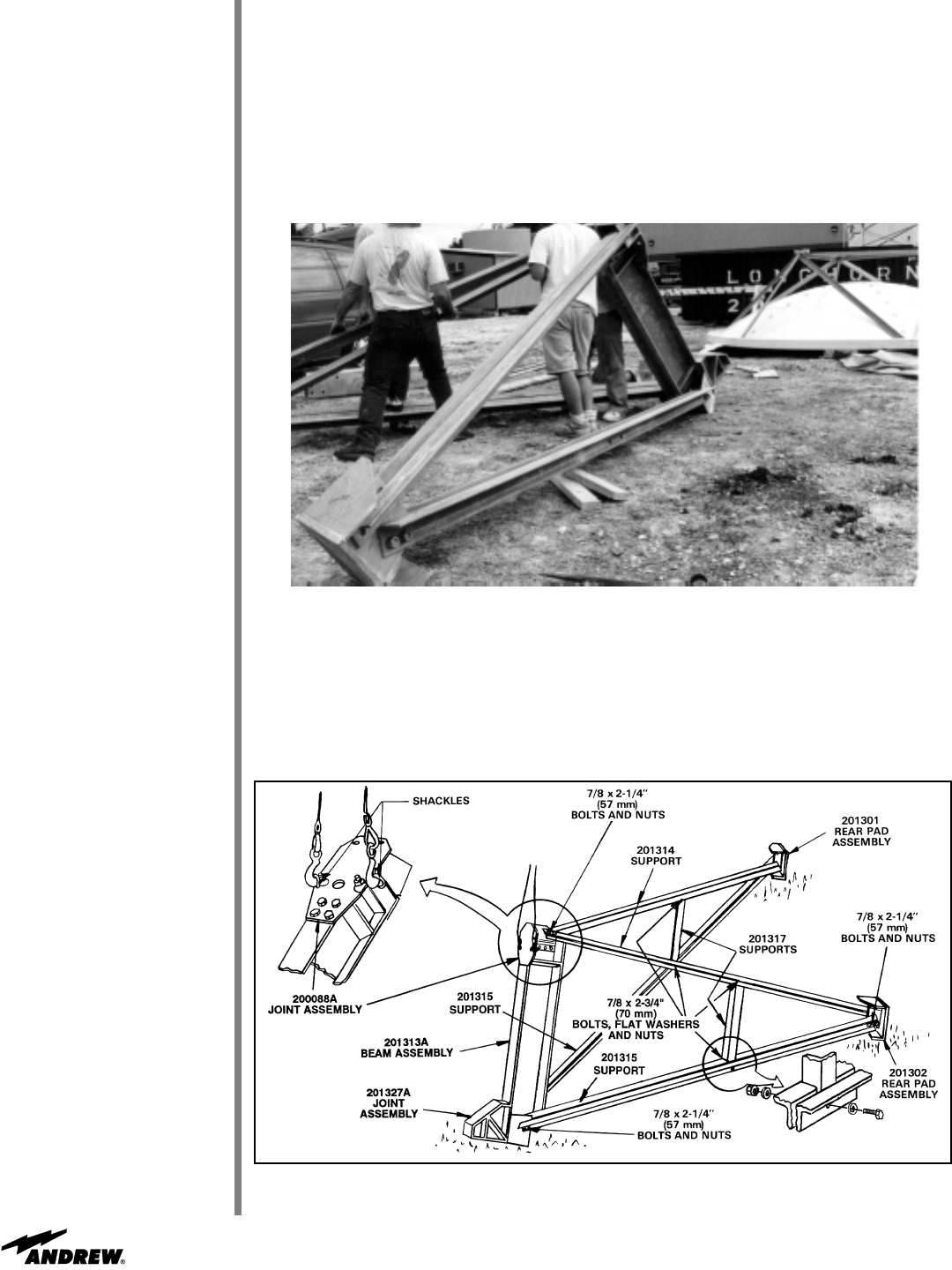
Attach 201314 supports to 201301/201302 rear pad assemblies and 200884 joint
assembly as shown in Figure 9.
• Use 7/8 x 2-1/4 in. (57 mm) bolts and nuts
•
Insert bolt from inside of joint assembly to outside of support
• Supports should be installed back-to-back with the edges forward and the flats of
angles facing rear
Installation Procedures
Figure 9
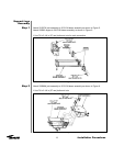
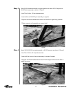
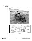
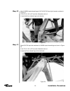
Attach 201317 supports between angle pairs as shown in Figure 10. Select correspond-
ing mounting holes so that 201317 supports are parallel to 201313A beam assembly.
• Use 7/8 x 2-1/4 in. (57 mm) hardware
• Supports attached with edges inward and flats facing up.
Figure 10