


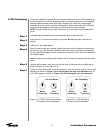


Step 3
Step 4
18
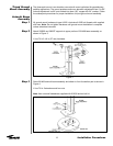
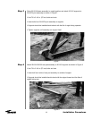
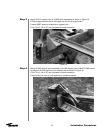
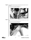
Attach 201316 support pairs to 221608 joint assemblies as shown in Figure 15.
• Place supports back-to-back with edges out and flat of angle inward
• Install 45967 spacer at midpoints of support pairs
• Use 7/8 x 2-1/4 in (57 mm) hardware for each connection
Installation Procedures
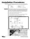
Figure 15
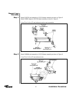
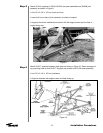
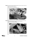
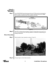
Attach 221345 azimuth pivot assembly to 201316 support pairs. Attach 201596 mount-
ing plates to 201458 azimuth pivot assembly tab as shown in Figure 16.
• Use 7/8 x 2-1/4 in (57 mm) hardware for each connection
• Insert bolts from rear of pivot assembly to connect supports
Figure 16