


Circuitry
The amplifier is totally complementary from input to output. This is achieved by using dual-differential input stages.
Full-complimentary push-pull pre-drivers follow the input stages. These in turn are direct-coupled (all stages after the
AC coupled input are DC coupled) to two push-pull drivers. All stages up to this point are operated in true Class A.
The drivers then drive the full complementary output stage.
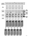
The power supply section of the amplifier consists of a highly efficient silicon steel (grain oriented) toroidal transformer
core that has separate bifilar wound secondaries to provide excellent voltage regulation and current reserve. A further
benefit of this transformer design is the low operating temperatures. The filtering section of the power supply for each
channel consists of two 8,200 microfarad capacitors. Thus, the AT6012 has a total of 196,800 microfarads capacitance.
The AT6012 is equipped with a thermal protection circuit for each zone. If the temperature of a heatsink reaches 85
0
C,
that zone will shut down. The thermal protection circuit may be triggered by excessive power demands into lower
impedance speakers than the amplifier is designed to drive or by inadequate ventilation. The amplifier will resume
normal operation when the heatsink returns to a safe operating temperature. Lowering the volume, correcting the low
impedance problem or providing proper ventilation may remedy this condition.
AC Line Connector And Power Cord
The AT6012 is supplied with a 15 Ampere, internationally-approved (IEC) power line connector which accepts the
supplied detachable, high-current capacity, power cord.
WARNING: UNDER NO CIRCUMSTANCES SHOULD THE ROUND THIRD PRONG BE CUT, BENT OR IN ANY
WAY DEFEATED AS THIS MAY RESULT IN SEVERE SHOCK.
AC Fuse
Your amplifier is supplied with a 15 Amp, 125V 3AB fuse. The fuse is located on the back panel. Should the fuse blow,
replace only with the same value. Use of any other value may cause damage to the amplifier and void the warranty.
WARNING: ALWAYS TURN OFF THE AMPLIFIER AND UNPLUG THE POWER CORD BEFORE REPLACING
ANY FUSE OR MAKING ANY ELECTRICAL CONNECTIONS.
Detachable Modular Component (DMC
4
)
Your AT6012 employs a unique Detachable Modular Component (DMC
4
) design which provides unit-to-unit quality
consistency as well as efficient serviceability. In the unlikely event of a channel failure, the module may be removed
for servicing thereby eliminating the need to return the whole unit.
CAUTION: IN NO CASE SHOULD YOU REMOVE THE MODULE BY YOURSELF. CONSULT WITH YOUR
DEALER OR ATI FOR PROPER DIAGNOSIS OF THE PROBLEM.
Page 11