


Page 8
Electrical Connections
In order to have the wiring concealed, all electrical connections are made in the rear of the amplifier.
CAUTION: ALL CONNECTIONS SHOULD BE MADE WITH THE AC POWER CORD UNPLUGGED AND
THE POWER SWITCH IN THE STANDBY (OFF) POSITION. UNDER NO CIRCUMSTANCES SHOULD
CONNECTIONS TO EITHER THE INPUT OR OUTPUT JACKS BE MADE WITH THE POWER ON.
Input Connections
Well-shielded audio cables should be used for the input connections. The input jacks have been gold-plated to provide
low contact resistance, long life, and minimal susceptibility to corrosion. Be sure to use only high-quality coaxial cables
with standard RCA-type pin jacks to connect the amplifier to a preamplifier or the main output terminals of the control
unit. DO NOT common ground the input grounds with the output ground (black) terminals.
Zone Volume Controls
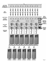
The AT6012 is equipped with six 2-channel connectors marked Zone 1 through Zone 6. These connectors are Phoenix™
type 3-pin connectors. The volume controls are motorized to ensure the quietest operation and lowest possible distortion.
Adjustment of these controls may be made via cabling from a control source or manually by using “momentary
switches”. The controls may also be adjusted by simply closing the contact of the “up” or “down” with the “common.
Output Connections
The output connections are gold-plated binding posts which will accept bare or soldered wire, spade lugs, or banana
jacks. This type of connector provides a solid connection with the speaker wires and eliminates the potential for
electric shock. The outputs are marked Zone 1 through Zone 6.
Loudspeaker Phasing
To obtain proper phasing and correct bass response, it is necessary that all channels be connected in phase.
The correct phasing occurs when speakers move in and out in unison (in phase) on monophonic program material.
Speakers connected in phase ensure proper imaging (placement of instrument and vocalist) while an out-of-phase
connection causes indistinct or confused imaging. The simplest way to effect proper phasing is to closely inspect the
cable being used for some form of wire coding. Some forms of wire markings are a ridge or a groove on one side of
the wire, one lead copper colored while the other is silver colored, or a colored stripe on one edge. The marked side
should be attached to the positive (red) terminals of each loudspeaker and the other end attached to the positive (red)
terminal of the corresponding channel’s binding post. Follow this procedure for all channels.