


©American Audio® - www.americanaudio.us - XLT Series Power Amplifier User Manual Page 13
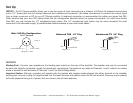
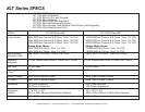
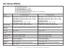
8-Ohm Loads: The amplifier can operate at practically any power level without risk of overheating. However, if it is pushed hard
enough to continually light the “CLIP” indicator, the amplifier’s average output power can reach 150 watts.
4-Ohm Loads: If the “CLIP” indicator flashes occasionally, the amplifier is approaching its maximum long-term power capacity. If it is
lit about half the time, the amplifier channel will probably go into thermal protection within a few minutes.
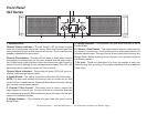
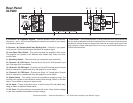
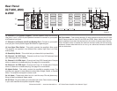
AMPLIFIER FEATURES:
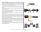
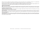
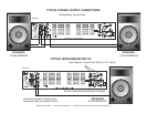
LINK - Link will allow the user to daisy-chain one amplifiers signal input into another amplifier. Plug the signal source outputs into the
first amplifier’s input, patch from the amplifier’s LINK jacks to the next amplifier’s input, and so on, daisy-chaining as many amplifiers
as there is no excessive level loss.
OPERATING VOLTAGE (AC MAINS) - The correct AC main voltage is listed above the Power Cord input. Connecting to the wrong
voltage is dangerous and may damage the amplifier.
GAIN CONTROLS - The gain controls are located on the front panel and are calibrated in 2dB of attenuation from full gain. It is best to
adjust the amplifier so no “hissing” is heard from speakers with no music being played, this will ensure the lowest possible distortion
during normal operation.
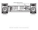
LED INDICATORS - Each channel has seven LEDS. The bottom LED is the channel power indicator. The next four LEDs indicate sig-
nal level activity; 3 green LEDs and one orange LED. One red LED indicates signal clipping and the other red LED indicates protec-
tions mode for shorts/ overload.