


9
2
NOISE GATE
You can set the MAXIDRIVE3.4 PC to cut the signal if it falls below a certain level. Most often used to cut
the background noise between music tracks.
3
PARAMETRIC EQUALIZATION (EQ)
Each of the channels (both inputs and outputs) has a fully variable 5-band parametric equalizer.
4
MASTER DELAY
Allows a delay to be applied to the signal fed from one or both of the input channels.
5
CHANNEL DELAY
Allows a delay to be applied in order to "time align" each individual output channel. Includes a graphical inter-
face of 6 virtual speakers.
6
CROSSOVER (XOVER)
The MAXIDRIVE3.4 PC is equipped with independent HIGH-PASS and LOW-PASS filters on each of the 6 output
channels. For each filter there are 10 different filter type/slope options.
7
PARAMETRIC EQUALIZATION (EQ)
Each of the channels (both inputs and outputs) has a fully variable 5-band parametric equalizer.
8
DYNAMIC GAIN CONTROL (CMP/LIM)
Each output channel has its own independent COMPRESSOR/LIMITER. Careful setting of the parameters
will help to maintain a more consistent and pleasurable listening level and extend the performance of your
speakers.
PRINT: Not a tabbed 'page' like those above, but an important function worth highlighting here. From the FILE
menu, selecting provides a print-out of all the parameters of the MAXIDRIVE3.4 PC, together withPRINT
the GLOBAL graph. View it before printing by selecting .PRINT PREVIEW
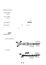
5. PARAMETER MENUS DESCRIPTION
1
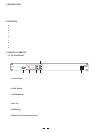
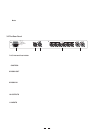
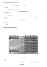
GAIN control section
The MAXIDRIVE3.4 PC has no analog input or output gain controls - level adjustment is handled entirely in the digital
domain. The input stage will accept a maximum input level of 2.2V rms.
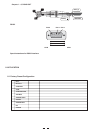
Click on one of the virtual level slide controls with your PC's left mouse button and hold the button down as you
move the virtual slider up or down with your cursor control. Alternatively, you can enter a dB value directly into the
text box below the slider (type a value and then press on your PC keyboard).ENTER
Clicking on a button (it will then turn red) will switch out that channel (useful during fault finding and systemMUTE
set-up). Channel signal (polarity) can be set to 0 or 180 degrees. This can sometimes improve stereoPHASE
imaging where speakers are mounted substantially off-axis. It can also provide a "quick fix" if you find you have
wired speakers out of phase!
2
NOISE GATE
This acts rather like a water-tight valve, allowing signal to pass or not pass through it. Every audio system, espe-
cially a complex one, produces some background noise. By setting the point (level threshold) below which the
gate closes, it is possible to minimize noise at those times when it is most likely to be audible, such as during the
pauses between tracks on a CD.
The Noise Gate cuts signal output whenever it drops below a selectable . The setting dic-THRESHOLD RANGE
tates the level range through which the gate will remain closed (usually this will be set to 80dB). The andATTACK
RELEASE times relate to the speed with which the Gate closes and opens. The default settings will usually be
fine and provide gating that works transparently, but you can use these settings to optimize the results if you hear
any side-effects.
GLOBAL: Within the PC Editor's tabbed menu view, you will see a tab labelled "Global" on the far right. This
window shows the response curves of all channel outputs and provides a convenient overview of your settings.
Each gate can be switched in or out of the audio circuit by clicking on the button. The button will turn redOFF/ON
when the Noise Gate is selected.