


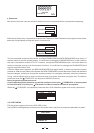
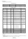
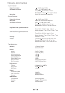


Parameter Controller Value setting Legend
Bank 0 0,1,2
Mode Channel
Mode Channel
22
22
0, 1
2, 3, 4, 5, 6, 7
Input Left, Input Right
Output 1, 2, 3, 4, 5, 6
Output Volume 7 0,..., 48 Select Mode Channel
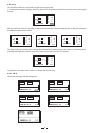
12 / 12 dB
High Pass Filter
High Pass Filter
17
17
0,..., 120
0, 1, 2, 3, 4
Mode Channel = 2, 3, 4, 5, 6, 7 Bank=0
Mode Channel = 2, 3, 4, 5, 6, 7 Bank=1
HP Frequency
HP Order
Low Pass Filter
Low Pass Filter
18
18
0,..., 120
0, 1, 2, 3, 4
Mode Channel = 2, 3, 4, 5, 6, 7 Bank=0
Mode Channel = 2, 3, 4, 5, 6, 7 Bank=1
LP Frequency
LP Order
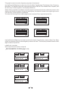
Delay Line Adj
Delay Line Fine
19
19
0,..., 127
0,..., 95
Mode Channel = 0, 1, 2, 3, 4, 5 Bank=0
Mode Channel = 0, 1, 2, 3, 4, 5 Bank=1
508 ms step 4ms
1995 us step 21us
Limiter Threshold
Limiter Release
Limiter Attack
20
20
20
0,..., 29
0,..., 3
0,..., 3
Mode Channel = 2, 3, 4, 5, 6, 7 Bank=0
Mode Channel = 2, 3, 4, 5, 6, 7 Bank=1
Mode Channel = 2, 3, 4, 5, 6, 7 Bank=2
29, ..., 0dB
0.4s, 0.5s, 0.7s, 1.4s
0.05s, 0.1s, 0.2s, 0.3s
Polarity
Polarity
21
21
0
1
Mode Channel = 2, 3, 4, 5, 6, 7
Mode Channel = 2, 3, 4, 5, 6, 7
Direct
Invers
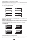
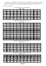
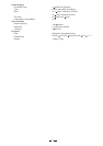
Filer 01, 02,..., 04
Filer 01, 02,..., 04
Filer 01, 02,..., 04
12, 13, 14, 15
12, 13, 14, 15
12, 13, 14, 15
0,..., 120
0,..., 60
0,..., 59
Only Mode Channel = 0, 1 (in L, R)
Only Mode Channel = 0, 1 (in L, R)
Only Mode Channel = 0, 1 (in L, R)
Frequency; Bank=0
Amplitude; Bank=1
Band Width; Bank=2
Filer 01, 02,..., 05
Filer 01, 02,..., 05
Filer 01, 02,..., 05
12, 13, 14, 15, 16
12, 13, 14, 15, 16
12, 13, 14, 15, 16
0,..., 120
0,..., 60
0,..., 59
Only Mode Channel = 2, 3, 4, 5, 6, 7
Only Mode Channel = 2, 3, 4, 5, 6, 7
Only Mode Channel = 2, 3, 4, 5, 6, 7
Frequency; Bank=0
Amplitude; Bank=1
Band Width; Bank=2
Mute
Mute
Mute
Mute
Mute
Mute
23
23
23
23
23
23
0, 1
0, 1
0, 1
0, 1
0, 1
0, 1
Output 1 Mute OFF, ON
Output 2 Mute OFF, ON
Output 3 Mute OFF, ON
Output 4 Mute OFF, ON
Output 6 Mute OFF, ON
Output 5 Mute OFF, ON
ModeCh=2
ModeCh=3
ModeCh=4
ModeCh=5
ModeCh=6
ModeCh=7
Routing 24 0,1 Connect Off/On InputL/R to Output1 Bank=0/Bank=1
Routing 25 0,1 Connect Off/On InputL/R to Output2 Bank=0/Bank=1
Routing 26 0,1 Connect Off/On InputL/R to Output3 Bank=0/Bank=1
Routing 27 0,1 Connect Off/On InputL/R to Output4 Bank=0/Bank=1
Routing 28 0,1 Connect Off/On InputL/R to Output5 Bank=0/Bank=1
Routing 29 0,1 Connect Off/On InputL/R to Output6 Bank=0/Bank=1
Parameter Value Legend
Preset 01 0 Preset Factory
Preset 02 to preset 64 1, 2, 3,......, 64 Preset User
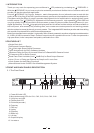
6. APPENDIX
AltoDrive3.4 Midi standard control
PROGRAM CHANGE
CONTROL CHANGE
Note:
Warnings:
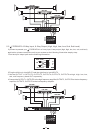
Select the channel to edit by means of the controller 22 (Mode channel).
1. Before starting a MIDI session please set on the ALTODRIVE3.4 the same MIDI channel used by the
external controller.
2. During a MIDI control session the unit's graphic display is NOT updated.
14