


C31/P35/P1
E-12
C31/P35/P1
E-13
English
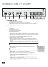
Connecting loudspeakers
Wiring strategies
There are three different wiring strategies that can be employed to connect your ampli er to your
speakers. The choice will be limited by what your speakers can support.
<
Single wiring
Single wiring is the conventional wiring method of running a single cable per channel between the
ampli er and the speaker. This is the easiest technique.
<
Bi-wiring
Bi-wiring is running two separate cables between the ampli er and each speaker, with one cable
carrying the low-frequency information, the other the higher-frequency signals. The P35 and P1
are designed to allow easy bi-wiring, but speakers support it only if separate connection terminals
are provided for the two cables (the speaker will have two pairs of terminals on the back, one pair
labelled ‘HF’ or ‘High Frequency’, the other pair labelled ‘LF’ or ‘Low Frequency’).
Why is this useful?
Bi-wiring improves the sound of your system because the separation of high- and low-frequency
signal currents into separate speaker cables avoids distortions caused by the different currents
interacting with one-another within a single cable, as occurs in single-wired systems.
<
Bi-amping
Bi-amping is the separation of the ampli cation of low- and high-frequency signals over two
ampli ers. You will require two ampli ers to do this.
Why is this useful?
The performance of your system is enhanced over bi-wiring by extending the signal separation
principle to use separate ampli cation for the low and high frequency drivers in each speaker.
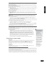
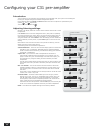
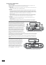
Single wiring
Both the P35 and the P1 are designed for bi-wiring, which
is why there are duplicate speaker terminals on the back.
Both amps are quite happy with single-wiring, however; we
recommend that you use the lower sets of speaker terminals
(labelled ‘SP1’ on the P35) in this case. Similarly, if your
speaker has more than one pair of connecting terminals, use
the terminals labelled ‘LF’ or ‘Low Frequency’ on the speaker.
For the P35, connect the positive terminal of the right
speaker connection on the ampli er (coloured red and
labelled ‘+R’) to the positive terminal of your right speaker.
Similarly, connect the negative terminal of the ampli er
(coloured black and labelled with ‘R–’) to the negative
terminal of your speaker. Repeat the process for the left
speaker, using the ampli er terminals labelled ‘+ L –’.
For the P1, connect the positive speaker terminal (coloured
red and labelled ‘+’) to the positive terminal of the speaker to be driven. Similarly, connect the negative
terminal of the ampli er (coloured black and labelled ‘–’) to the negative terminal of the same speaker.
Repeat the process for your other P1 and speaker.
If your speakers support bi-wiring, then there is a strip of metal on the speakers connecting the low-
frequency terminals to those for the higher-frequencies; this must not be removed in a single-wired
system.
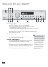
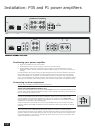
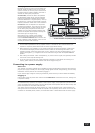
Bi-wiring
Bi-wiring is performed in the same way as single
wiring except that, for each speaker, a pair of cables
are used to connect the ampli er to each speaker.
Follow the instructions given for single wiring; then
perform the same actions, this time connecting the
second set of speaker terminals (labelled “SP2” on
the P35) to the speaker terminals labelled ‘HF’ or
‘High Frequency’. Please refer to the illustration.
Speakers that support bi-wiring have a strip of
metal on the speakers connecting the low-frequency
terminals to those for the higher-frequencies; this
must be removed in a bi-wired system.
A P35 connected to speakers using bi-wiring.
A P35 connected to speakers using single wiring.