


C31/P35/P1
E-10
C31/P35/P1
E-11
English
Installation: P35 and P1 power ampli ers
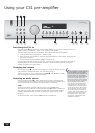
Positioning your power ampli er
<
Place your ampli er on a rm, level surface.
<
Avoid placing the unit in direct sunlight or near sources of heat or damp.
<
Ensure adequate ventilation. Do not place the your ampli er in an enclosed space, such as a
bookcase or cabinet, as both of these will impede air- ow through the unit (which is necessary for
cooling).
In most situations, there are two choices for getting signals from the P35 to the speakers: the P35 can
be situated remotely from the speakers and longer speaker cables used, or the P35 can be situated
locally to the speakers by using longer line-level cables (from the pre-ampli er). Over long distances
(5m+), the sound quality will generally be better using the low-current line-level (pre-ampli er) cabling
than high-current speaker (post-amplifer) cabling, due to otherwise high losses in the speaker cabling.
Connecting to other equipment
The P35 and P1 ampli ers provide the following connections:
AUDIO IN (P35)
AUDIO IN and BALANCED AUDIO IN (P1)
Connect the output sockets of your pre-amp. (or the PRE OUT sockets of an integrated ampli er) to one
of these inputs. Please read the information on page 5 “Power-ampli er connections”, which details the
type of connection that should be used.
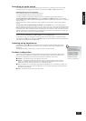
Mono Link (P35)
The P35 can be adapted to provide two mono loudspeaker outputs from a single input. Pull out
the link supplied on the back panel (labelled ‘link’) and use it to connect the L and R AUDIO OUT
sockets together. Using one power ampli er per loudspeaker will enable you to bi-amplify bi-wireable
loudspeakers (as described on the following page).
Follow the instructions given below for bi-wiring, using the SP2 connections of the P35 for the high-
frequency speaker and the SP1 connections for the low-frequencies. See also the section on “Remote
switching”.
Input Selector Switch (P1)
This switch allows either unbalanced signals (through the phono connector) or balanced signals
(through the XLR connector) to be selected. The switch should be pressed-in to select the phono inputs
and out to select the XLR connector. Note that only one type of input connector will be switched to the
input of the ampli er; if you select (for example) the XLR connector, then you will not be able to hear
signals connected to the phono inputs.
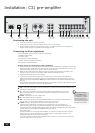
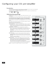
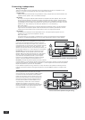
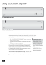
P35 Power Ampli er: rear panel
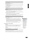
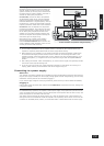
P1 Power Ampli er: rear panel
P35 Power Ampli er: rear panel
+ R/CH1 –
SP1
SP2
POWER INLET
OUTIN
L
R
VOLTAGE
SELECT
230V
4 – 16 OHMS
+ L/CH2 –
+ R/CH1 –
+ L/CH2 –
AUDIO
LINK
REMOTE
IN
TRIG
OUT
P1 Power Ampli er: rear panel
POWER INLET
OUT
VOLTAGE
SELECT
230V
GAIN
XLR/
PHONO
TRIG
OUT
REMOTE
IN
4 – 16 OHMS
–
+
SPEAKERS
–
+
AUDIO
IN
P1
ARCAM
XLR
PHONO
BALANCED AUDIO
OUT
IN
The mono link fitted