


PLM Series Network Configuration Guide 9
NeTwORk CONNeCTIONS aND TOPOLOgIeS 5
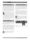
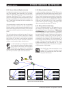
5.2.3 Daisy-chained switches
In such a topology, each group of PLM Series units
(typically those inside the same rack) have a switch
inside the rack to which each has a direct connection.
These “local” switches are connected in a daisy chain
(figure 5.2.3). Systems of this type can be made quite
large if the switches are using 1000BASE-T (Gigabit
Ethernet), and although this is a very convenient
system when it comes to wiring, a topology of this
type can potentially develop SPF issues.
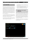
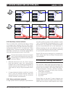
5.2.4 Daisy-chained switch ring
This is an enhanced variant of the above that can
be created if the switches support RSTP, or Rapid
Spanning Tree Protocol. (See section 7, References
and Definitions, for more information.) The benefit
of this configuration is that, if there is a cable failure,
the network will recover; all devices on the network
(PLMs, switches, routers, etc.) will still be able to
communicate. If a switch fails, all devices will remain
connected to the network, with the exception of
those devices that are directly connected to the failed
switch. If Dante is being used, there will be a brief
audible interruption in the sound (5 ms – 2 s), the
length of which will depend on the size of the system
and the vendor of the switch.
The PLM’s own internal switches do not
support RSTP. Care must be taken to not
create a ring (closed loop) with the PLM’s
rear panel connectors.
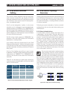
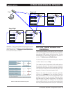
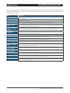
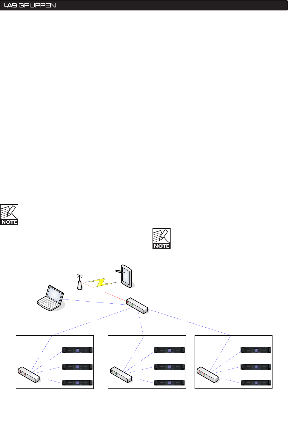
5.2.2 Star or Hub-and-Spoke networks
An alternative approach is to implement a network
with Star topology, also referred to as ‘hub-and-
spoke’ or ‘radial’ topology, using a number of Ethernet
switches. (See figure 5.2.2.) In such a network, a
group of PLMs (typically those inside the same rack)
are connected directly to a switch also housed in the
rack. These local switches are then connected to a
“central” switch.
If dual redundancy mode is used, then a completely
parallel secondary network can be created. The
primary network would connect the primary port of
each Dante equipped device (PLM or DLP) and the
secondary network would connect all the secondary
ports.
The dual redundancy mode has the benefit that any
single switch can fail without causing an audible
interruption in the network. However, the control
and monitor PC will have to be manually switched
between the primary and the secondary network if
a failure on one network layer should occur.
A dual redundancy configuration doubles
the number of switches and cables needed.
Also note that the Dolby Lake Processor
(DLP) does not support this redundancy
scheme via dual rear panel Ethernet connectors, so
one DLP per network layer would be required.
1000 1000
Rack
1000
1000
1000
802.11g/n
100
100
100
Rack
1000
100
100
100
Rack
1000
100
100
100
Figure 5.2.2: Two level star topology