


10 PLM Series Network Configuration Guide
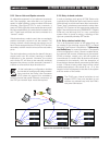
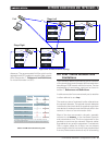
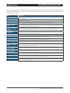
may be to place a group of local switches in each
“zone”, which are first interconnected to form a “local
area network” (e.g. Stage Left). These area networks
are then interconnected with a main backbone. A
different topology for the main backbone than that
of the local area network may be chosen, depending
on your specific application and resources.
Figure 5.2.6 shows an example of a combined net-
work utilizing both Star and Daisy Chained switch
ring topologies.
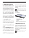
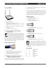
5.3 Ethernet Cabling Limitations
The maximum cable length allowed between any
two devices on a network is defined by the Ethernet
protocol and is limited to 100 meters (330 feet) for
copper connections. The term “devices” includes:
The host PC running the Dolby Lake Controller •
PLM Edition software
Any switch on the network•
Any access point•
Any PLM•
Optical fiber can be used if longer distances are
needed. Multi-mode fiber supports up to 550 meters
(1800 feet) and single mode supports even longer
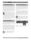
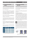
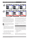
5.2.5 Dual daisy-chained switches
This is a hybrid that combines the ease of wiring
of the daisy chain topology with the 100% avoid-
ance of SPF issues in the dual redundant star/spoke
configuration (figure 5.2.5). It is simply two “daisy
chained switch” networks in parallel: the primary and
secondary networks are connected independently
using the dual redundant mode in the PLMs.
If the control computer only has one network
card, it can be connected to only one of the
network layers. The solution to this situation
can be as follows:
Manually disconnect from the “blue“ network •
layer and connect to the “red” network layer
instead if one or more PLMs are inaccessible via
the blue network (see figure 5.2.5). This can be
done easily by using a simple hardware switch
box.
A more advanced solution would be to equip
•
the PC with two identical network cards and
appropriate drivers so that it can be connected
to both networks simultaneously.
5.2.6 Other combination networks
In larger system network topologies, a good solution
1000
Rack
1000 1000
1000
100
100
100
1000
Rack
1000
100
100
100
1000
Rack
1000
100
100
100
1000
Rack
1000 1000
1000
100
100
100
1000
100
100
100
1000 1000 1000
Rack
1000 1000
100
100
100
1000
100
100
100
1000 1000 1000
Rack
1000
100
100
100
1000
100
100
100
1000 1000
Figure 5.2.3: Daisy chained switches
Figure 5.2.5: Dual daisy chain switch topology
5 NeTwORk CONNeCTIONS aND TOPOLOgIeS