


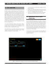
PLM Series Network Configuration Guide 11
5.4 PLM / Dante Network Size
Limitations
The information below is provided to give an overview
of the terminology and concepts that are used when
describing a PLM network and its functions. Further
explanations of terminology used can be found in
section 7, References and Definitions.
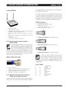
A cable connection from one network port to another
is often referred to as a hop.
The maximum size of a network is often referred to as
the network diameter. The optimal network diameter
is defined by the time it takes for a packet to get from
one device to another across the furthest point in the
network, in terms of communication time.
Most of the time consumed in the path, generally
referred to as latency, is the hardware reaction
and transmission time. The time consumed for the
packets to travel over the network Ethernet cables
themselves is very small in comparison. If we assume
100 m copper cables for all hops, we can present
some simple rules for how many hops are permitted
from any Dante source device to any of its recieving
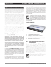
distances. The recommended LinkSys switch can be
upgraded with SFP modules to support fiber connec-
tions (See section 7, References and Definitions,
for more information on SFP.)
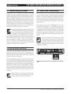
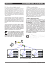
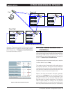
Rack
1000 1000
100
100
100
1000
Rack
1000
100
100
100
1000
1000
Stage Right
1000
Rack
1000
100
100
100
1000
Rack
1000
100
100
100
1000
1000
Stage Left
FoH
1000
1000
1000
1000
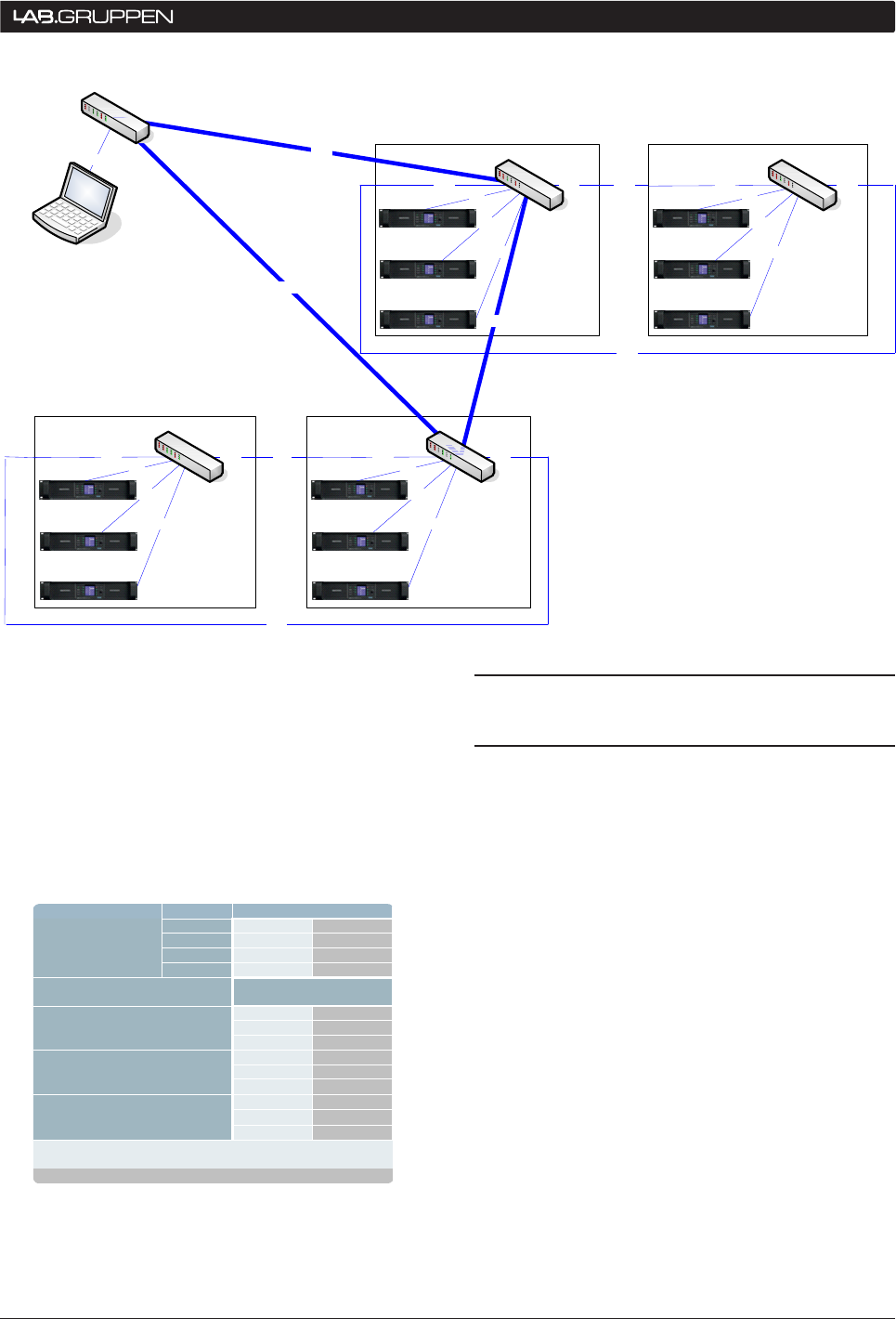
Figure 5.2.6: Combined network topology
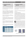
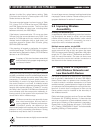
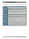
Link speed [Mbps]
System type 1* 2**
Source 100 100
Backbone 100 1000
Sink 100 100
Network diameter
[# of “hops”]
14 62
Latency setting 1 0.8 ms 1 4
1 1
2 9
Latency setting 1 1.3 ms 4 19
14 >20
56 256
Latency setting 2 4.0 ms 9 45
7 34
* PLM/DLP without external switches or with 100 Mbps switches
(not a recommended setup!)
** Recommended PLM only example with Gigabit switch backbone
Table 5.4: PLM network diameter guide
NeTwORk CONNeCTIONS aND TOPOLOgIeS 5