246815-YTG-D-0108
4 Unitary Products Group
FILTER PERFORMANCE
The airflow capacity data published in the “Blower Perfor-
mance” table listed above represents blower performance
WITHOUT filters. To determine the approximate blower per-
formance of the system, apply the filter drop value for the fil-
ter being used or select an appropriate value from the “Filter
Performance” table shown.
NOTE: The filter pressure drop values in the “Filter Perfor-
mance” table shown are typical values for the type of filter
listed and should only be used as a guideline. Actual pres-
sure drop ratings for each filter type vary between filter manu-
facturer.
NOTE: All filters must be high velocity cleanable type.
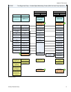
APPLYING FILTER PRESSURE DROP TO
DETERMINE SYSTEM AIRFLOW
To determine the approximate airflow of the unit with a filter in
place, follow the steps below:
1. Select the filter type.
2. Determine the External System Static Pressure (ESP)
without the filter.
3. Select a filter pressure drop from the table based upon
the number of return air openings or return air opening
size and add to the ESP from Step 2 to determine the
total system static.
If total system static matches a ESP value in the airflow table
(i.e. 0.20, 0.60, etc,) the system airflow corresponds to the
intersection of the ESP column and Model/Blower Speed row
.
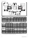
FILTER SIZES
CFM
Cabinet
Size
Top Return
Filter in
1200 B (2) 14 x 20
1600 C (2) 14 x 20
2000 C (2) 14 x 20
2000 D (2) 14 x 20
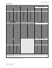
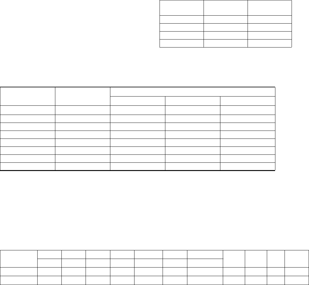
FILTER PERFORMANCE - PRESSURE DROP INCHES W.C. AND (KPA)
Airflow Range
Minimum
Opening Size
Filter Type
Disposable Washable Fiber Pleated
CFM
in
2
In W.C. In W.C. In W.C.
0 - 750 230 0.01 0.01 0.15
751 - 1000 330 0.05 0.05 0.20
1001 - 1250 330 0.10 0.10 0.20
1251 - 1500 330 0.10 0.10 0.25
1501 - 1750 380 0.15 0.14 0.30
1751 - 2000 380 0.19 0.18 0.30
2001 & Above 463 0.19 0.18 0.30
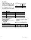
UNIT CLEARANCES TO COMBUSTIBLES
Application
Top Front Rear Left Side Right Side Flue Floor/Bottom
Closet Alcove Attic
Line
Contact
In. In. In. In. In. In. In.
Downflow1300 0 0
1
*
* Combustible floor base or air conditioning coil required for use on combustible floor.
Yes Yes Yes NA
Horizontal 0 3 0 1 1 0 0 Yes Yes Yes
Yes
†
† Line contact only permitted between lines formed by the intersection of the rear panel and side panel (top in horizontal position) of the furnace jacket and build-
ing joists, studs or framing.