Teledyne API T803 CO2/O2 Analyzer Operation Manual Principles of Operation
215
12.6.3. RELAY BOARD
The CPU issues commands via a series of relays and switches located on a
separate printed circuit assembly, called the relay PCA, to control the function of
key electromechanical devices such as heaters. The relay PCA receives
instructions in the form of digital signals over the I
2
C bus, interprets these digital
instructions and activates its various switches and relays appropriately.
The relay PCA is located in the right-rear quadrant of the analyzer and is
mounted vertically on the backside of the same bracket as the instrument’s DC
power supplies.
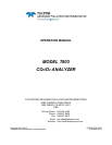
Power
Connection
for DC
Heaters
Status LED’s
(D2 through D16)
DC Power Supply
Test Points
Watchdog
Status LED (D1)
(JP5)
Thermocouple
Configuration
Jumpers
Thermocouple
Signal Output
I
2
C
Connector
alve Control
Drivers
Pump Power
Output
(JP7)
Pump AC
Configuration
Jumper
AC Power
IN
DC Power
Distribution
Connectors
alve Control
Connector
(J2)
Connector for
AC Relays
K4 & K5
(J18)
Connector for AC Relays K4 & K5
Heater AC Power
Configuration
Jumpers
JP2
JP6
Figure 12-9: Relay PCA Layout (PN 04135)
CAUTION
ELECTRICAL SHOCK HAZARD
Only those relays actually required by the configuration of the T803 are populated.
A protective retainer plate is installed over the AC power relays to keep them securely
seated in their sockets and prevent accidental contact with those sockets that are not
populated see Figure 12-10).
Never remove this retainer while the instrument is plugged in and turned on. The contacts of
the AC relay sockets beneath the shield carry high AC voltages even when no relays are
present.