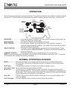
DV425TR DIRECT VENT ROOM HEATER
02/01 Page 37 250-5533
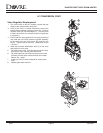
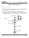
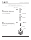
Step 1.
Follow installation Steps 1 and 2 under
vertical termination section.
Step 2.
Using the plumb-bob, mark the centerline of
the venting system on the ceiling, and drill a small
hole through the ceiling and roof at this point. From
the roof, locate the drill hole and mark the outline of
the cathedral ceiling support box.
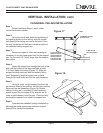
Step 3.
Remove shingles or other roof covering as
necessary to cut the rectangular hole for the support
box. Cut the hole 1/8” (3mm) larger than the support
box outline.
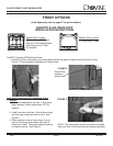
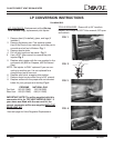
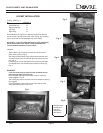
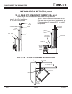
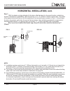
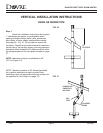
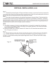
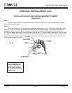
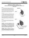
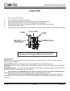
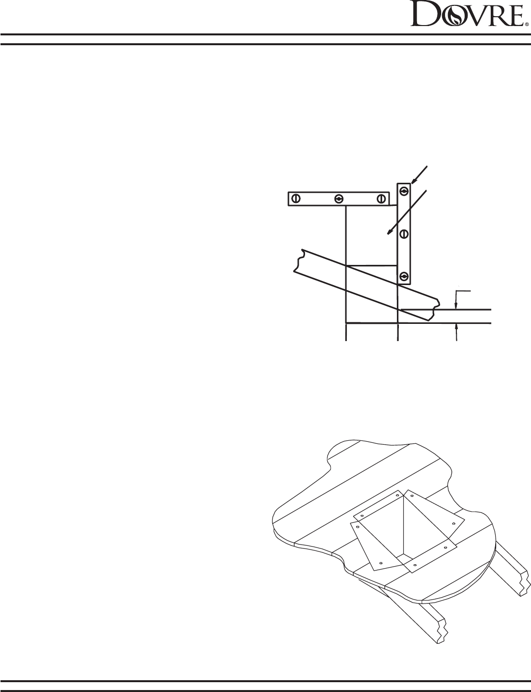
Step 4.
Lower the support box through the hole in the
roof until the bottom of the box protrudes at least
2” (51mm) below the ceiling (Figure 17). Align the
support box both vertically and horizontally with a
level. Temporarily tack the support box in place
through the inside walls and into the roof sheathing.
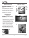
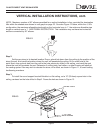
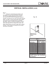
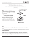
Step 5.
Using tin snips, cut the support box from the
top corners down to the roofline, and fold the resulting
flaps over the roof sheathing (Figure 18). Before
nailing it to the roof, run a bead of non-hardening
mastic around the top edges of the support box to
make a seal between it and the roof. Clean out any
combustible material from inside the support box.
Step 6.
Complete the cathedral ceiling installation by
following the same procedures outlined in steps 4
through 8 for vertical terminations.
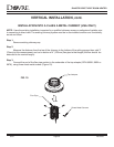
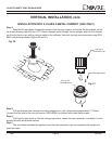
VERTICAL INSTALLATION, cont.
Figure 17
LEVEL
CATHEDRAL CEILING
SUPPORT BOX
2" MIN. BELOW
FINISHED CEILING
CUT HOLE 1/8"
GREATER IN SIZE
THAN PATTERN OF
SUPPORT BOX AS
IT IS PROJECTED
ONTO ROOF LINE
Figure 18
CATHEDRAL CEILING INSTALLATION