DV425TR DIRECT VENT ROOM HEATER
02/01 Page 28 250-5533
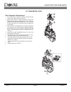
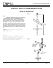
Step 1.
Determine the desired location of the stove. Check to ensure that wall studs or roof rafters are not
in the way when the venting system is attached. If this is the case, you may want to adjust the location of
the stove.
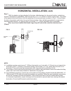
Step 2.
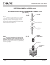
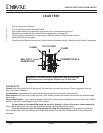
Simpson Dura-Vent pipe is designed with special twist-lock connections. To connect the venting system
to the stove flue outlet, a twist-lock adapter is built into the stove at the factory. Remember to include wall
thickness in minimum clearances when figuring the measurements for your installation needs.
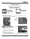
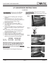
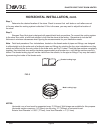
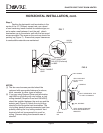
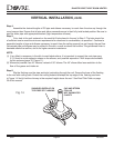
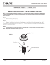
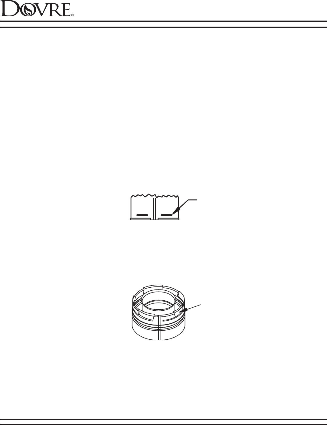
Note: Twist-lock procedure: Four indentations, located on the female ends of pipes and fittings, are designed
to slide straight onto the male ends of adjacent pipes and fittings by orienting the four pipe indentations so they
match and slide into the four entry slots on the male ends, see Fig. 5 below. Push the pipe sections completely
together, then twist-lock one section clockwise approximately one-quarter turn, until the two sections are fully
locked. The female locking lugs will not be visible from the outside, on the pipe or fittings. They may be located
by examining the inside of the female ends.
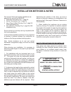
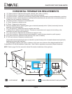
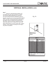
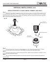
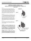
NOTES:
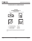
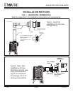
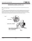
Horizontal runs of vent must be supported every 3’ (914mm). Wall straps are available for this purpose.
Horizontal sections require a 1/4" (6mm) rise for every 12" (305mm) of horizontal travel.
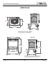
Exterior Vent Diameter = 6 5/8" (177mm); Inner Vent Diameter = 4" (101mm)
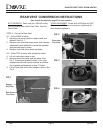
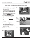
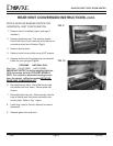
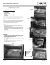
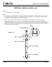
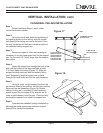
HORIZONTAL INSTALLATION, cont.
Male Locking Lugs
Female Locking Lugs
FIG. 5