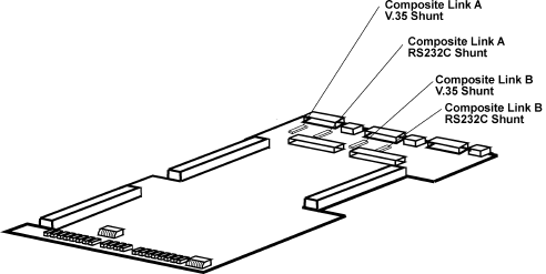
Figure 4-4. Shunts
11 Partially slide the Aggregate board into the chassis.
12 If the Voice/Fax board is in the chassis, connect the short ribbon cable between the Aggregate board and the
Voice/Fax board. This ribbon cable goes on the front left side of the Aggregate board and is the only
connector on the Voice/Fax board.
Table 4-2. V.35 Interface (Cont.)
Step Procedure
13 Reconnect the control ribbon cable on the right side between the Aggregate board and the Channel board(s).
WARNING
Make sure the ribbon cables are not crimped
and are tight or the entire MultiMux will be
damaged when power is applied.
14 Reconnect the data and address ribbon cable on the left side between the Aggregate board and Channel
Board(s).
15 Slide all the boards fully into the chassis. The Voice/Fax board (if installed) will require an extra push to seat it
in its board edge connector.
16 Ensure that the boards are seated into the back panel.
17 Ensure that the pc board chassis locks will seat into the boards. Then loosen, pry down and retighten the
screws.
Warning
Ensure that the power cable connector pins align
with the connector on the power supply board and
that the power cable connector has the locking notch
facing upward. If the cable is misaligned in any way
severe damage may occur to the unit.
18 Connect the pc board power cable to the power supply being careful that the pins are aligned properly. See
Figure 4-3.
19 Replace the front panel securing it to the chassis with the four quarter-turn-fasteners.
20 Connect a V.35 interface adapter cable (Multi-Tech #90056210) to the COMPOSITE LINK A or B (RS232C/
V.35) EXTERNAL MODEM/DSU connector(s) on the back panel and to the V.35 connector on the
external link device(s).
Table 4-3. Configuration Procedure
Step Procedure
1 Connect the AC power cord shipped with your MultiMux to the AC power connector on the back panel
and to the AC outlet.
2 Place the power ON/OFF switch on the back panel of the MultiMux to the ON position to apply power.
Supervisory Console
