OM-494 Page 20
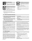
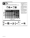
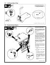
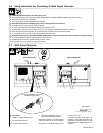
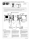
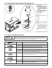
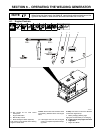
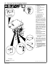
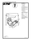
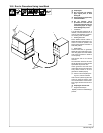
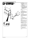
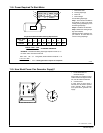
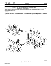
5-10. Making Dual Operator CV Weld Connections w/ Separate Work Cables
Ref. 190 377 / 802 292-A
Y Stop engine.
Y Do not exceed machine duty cycle.
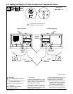
. Use Dual Operator mode for CC and
CV welding (see Section 6-1).
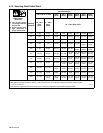
See Section 5-15 for proper cable size.
1 Strain Reliefs
Route cables through strain reliefs.
2 Wire Feeder Cables
3 Work Cables
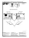
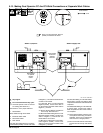
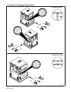
For MIG and FCAW welding Direct Current
Electrode Positive (DCEP), connect work
cables to Negative (−) terminals and wire
feeder cables to CV terminals.
For MIG and FCAW Direct Current Elec-
trode Negative (DCEN), connect work
cables to CV terminals and wire feeder
cables to Negative (−) terminals.
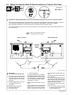
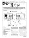
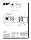
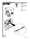
If unit has the Polarity switch option, con-
nect work cables to Work receptacles and
wire feeder cables to CV receptacles.
. Place optional Polarity switches in Re-
verse position when using CV weld re-
ceptacles. There is no CV weld output
when switch is in Straight position.
. Be sure Process Selector and Polarity
switches are set correctly. See Section
6-3.
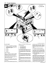
Tools Needed:
Welder A (Left) Side
3/4 in
Welder B (Right) Side
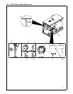
1
2
3
2
Direct Current Electrode Positive
(DCEP) connections are shown.
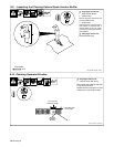
Note position
of Process
Selector
switches.
Note position
of optional
Polarity
switch.
Note position
of optional Po-
larity switch.