2-19
Installing the Switch
Installation Procedures
Installing the Switch
620 RPS/EPS Connectivity
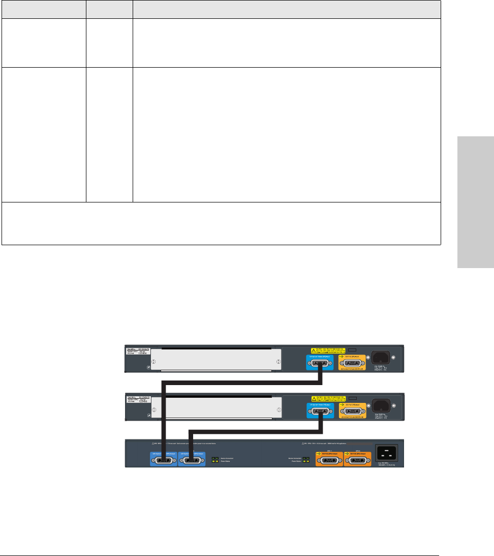
This section shows some recommended connection topologies using the 620
RPS/EPS. The 620 RPS/EPS can provide backup power support for up to two
HP ProCurve switches. In the illustration below, two HP ProCurve 3500yl-24G-
PWR switches are connected to the RPS ports on a 620 RPS/EPS.
Figure 2-13. Connecting RPS to two 24-port switches.
Device Connected
(green – over-laid
with the port
number)
On There is a valid connection to a device.
Off There is no valid device connected to the port.
Power Status
(green and orange)
On The unit is supplying power to a connected device.
Off One of these conditions exists:
• There is no connected device.
• A connected RPS device does not require power.
• A connected EPS device has not successfully communicated for EPS power.
Blink
orange
1
One of these conditions exists:
• On the 620 RPS/EPS, RPS power is not available to the connected device
because there is a hardware or power supply failure in the 620 RPS/EPS unit.
• When the LED is blinking simultaneously with the Fault LED, there is a fault
condition on the port.
1
The blinking behavior is an on/off cycle once every 1.6 seconds, approximately.
2
The blinking behavior is an on/off cycle once every 0.8 seconds, approximately.
3
Specific fault conditions can be viewed by checking switch log files.
LED State Meaning


