


Connections (Continued)
12
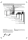
Basic TV Connections
Make one of the following connections, depending on
the capabilities of your TV.
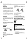
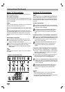
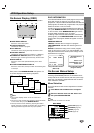
RF coaxial connection
Connect the RF.OUT jack on the DVD/VCR Receiver to
the antenna in jack on the TV using the 75-ohm Coaxial
Cable supplied (R).
ote
If you use this connection, tune the TV to the DVD/VCR
Receiver’s RF output channel (CH 3 or 4).
How to set the DVD/VCR Receiver’s RF output chan-
nel
While the DVD/VCR Receiver is turned off,
press and
hold CH/PRESET (v/V) on the front panel for about five
seconds to change the RF output channel (CH 03 or
CH 04). “RF 03” or “RF 04” appears in the display win-
dow.
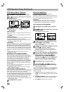
Audio/Video connection
11
Connect the DVD/VCR VIDEO OUT jack on the
DVD/VCR Receiver to the video in jack on the TV
using the supplied video cable (V).
22
Connect the Left and Right DVD/VCR AUDIO OUT
jacks on the DVD/VCR Receiver to the audio
left/right in jacks on the TV (A) using the supplied
audio cables.
ote
If you use this connection, set the TV’s source selector
to VIDEO.
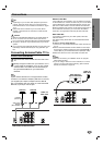
Optional TV Connections
ote
The S-VIDEO OUT and COMPONENT/PROGRESSIVE
SCAN VIDEO OUT connection options below only work
with DVD playback.
The tuner and VCR will still output
through the RF.OUT (R) or DVD/VCR OUT (A, V) jack.
(See left)
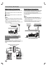
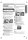
S-Video Connection
11
Connect the S-VIDEO OUT jack on the DVD/VCR
Receiver to the S-Video in jack on the TV using the
supplied S-Video cable (S).
22
Connect the Left and Right AUDIO OUT jacks on
the DVD/VCR Receiver to the audio left/right in
jacks on the TV using the supplied audio cables
(A).
Component Video (Color Stream
®
) connection
11
Connect the COMPONENT/PROGRESSIVE SCAN
VIDEO OUT jacks on the DVD/VCR Receiver to the
corresponding in jacks on the TV using user-sup-
plied Y Pb Pr cables (C).
22
Connect the Left and Right AUDIO OUT jacks of
the DVD/VCR Receiver to the audio left/right in
jacks on the TV (A) using the supplied audio
cables.
Progressive Scan (ColorStream
®
pro) connection
If your television is a high-definition or “digital ready”
television, you may take advantage of the DVD/VCR
Receiver’s progressive scan output for the highest
video resolution possible.
If your TV does not accept the Progressive Scan for-
mat, the picture will appear scrambled if you try
Progressive Scan on the DVD/VCR Receiver.
11
Connect the COMPONENT/PROGRESSIVE SCAN
VIDEO OUT jacks on the DVD/VCR Receiver to the
corresponding in jacks on the TV using an optional
Y Pb Pr cable (C).
22
Connect the Left and Right AUDIO OUT jacks of
the DVD/VCR Receiver to the audio left/right in
jacks on the TV (A) using the supplied audio
cables.
otes
– Set Progressive Scan to “On” on the DVD setup
menu for progressive signal, see page 21.
– Progressive scan does not work with the analog video
connections (yellow VIDEO OUT jack).
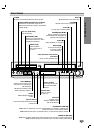
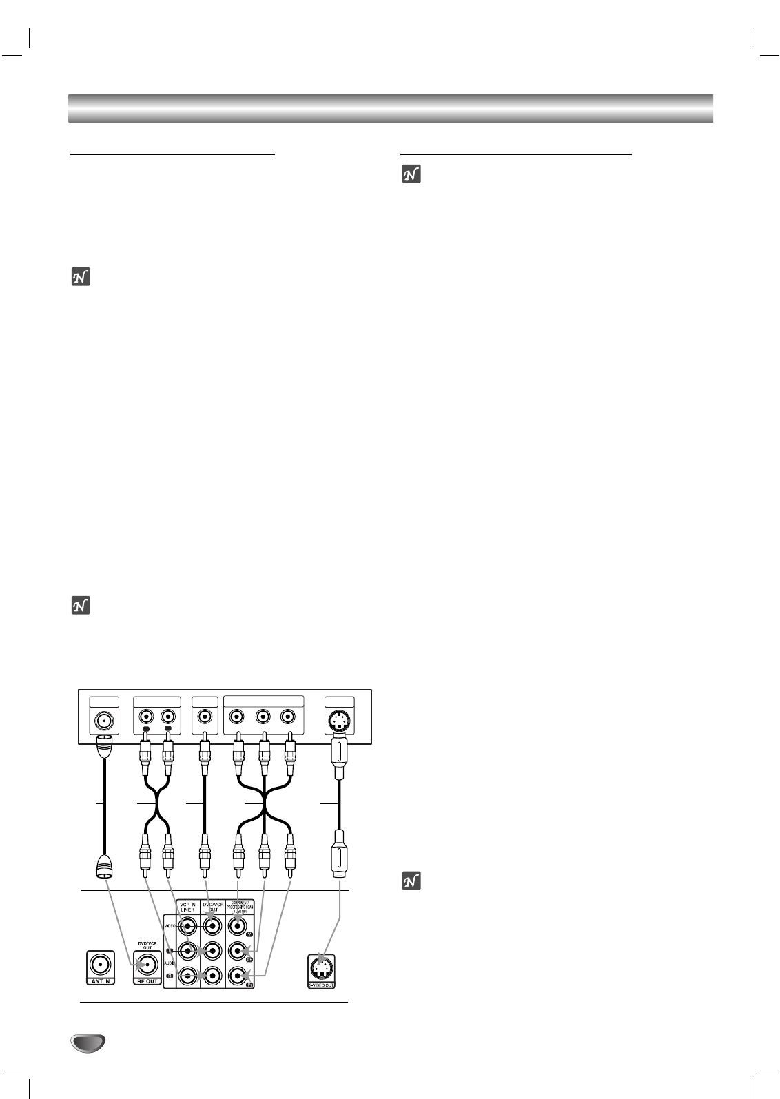
ANTENNA
INPUT
R
L
R
Y
Pb
Pr
COMPONENT/PROGRESSIVE
SCAN VIDEO INPUT
AUDIO INPUT
L
VIDEO
INPUT
S-VIDEO
INPUT
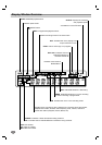
Typical TV Connections Panel
DVD+VCR Connections Panel
SA V C