


3
through Yorkville dealers. The foam filters should be removed if a
regular inspection schedule is not going to be followed. The amplifier
can operate without the filters in place, but the amplifier should be
cleaned internally by a qualified service technician when dust is vis-
ible on the heatsink fins. (see diagram, next page)
Note: In an unusually dusty location, without regular filter inspec-
tions, removing the foam filter can extend the operating time
before thermal shutdown could occur. At that time, the internal
heatsinks should be cleaned thoroughly.
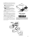
Output Connections
WARNING: When driven to full power, there is more than
100Vrms appearing between the binding posts. This represents a
significant shock hazard and due care should be taken when mak-
ing any speaker connections. Ensure that no strands of bare con-
ductor are exposed after inserting the speaker wire into the hole in
the side of the binding post terminals.
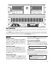
The AP6020 has 5–way binding posts and Neutrik four con-
tact SPEAKON™ connectors for output speaker connections.
Connection to the binding posts can either be made with a banana
plug inserted into the end of the post or by wires wrapped around
the threads and tightened.
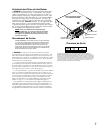
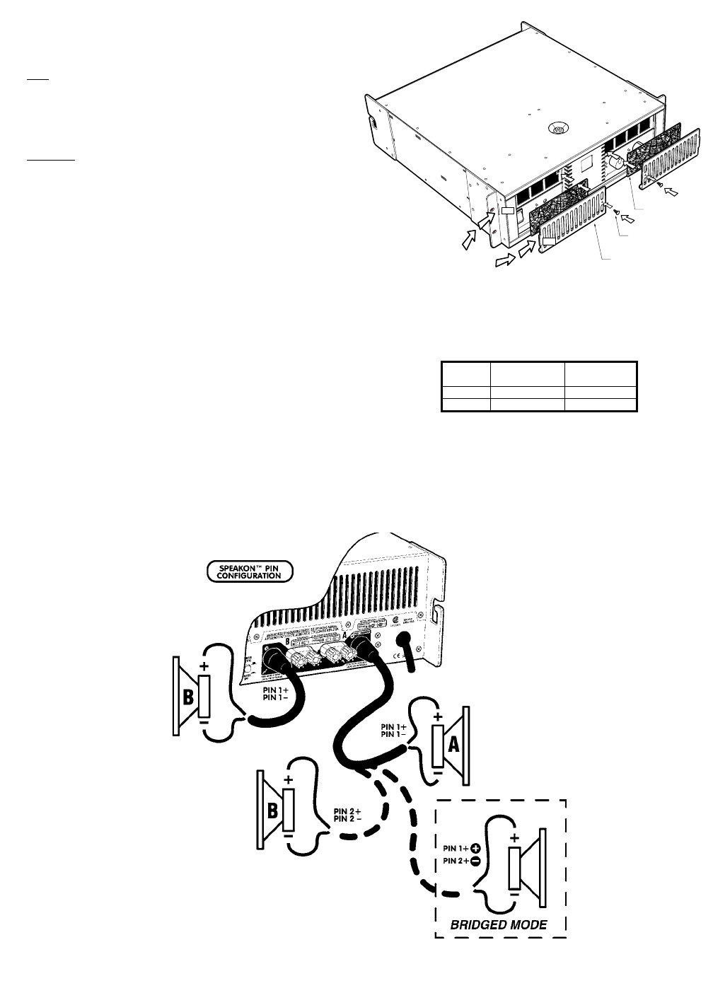
There are two SPEAKON™ connectors, one for each channel out-
put. All connectors are connected to the amplifier’s outputs whether the
amplifier is in stereo or mono modes. Connection configurations are
labeled on the back panel. Each SPEAKON™ output connector (output
A and output B) are wired in parallel with it’s respective binding post.
Speakon™ output A also doubles as the A&B/Bridge connector.
This Speakon™ contains both channels on one connector. This is con-
venient when connecting one speaker to the amplifier in bridge mode
where the speaker is connected across the positives of each amplifier
output. Configure the mode switch for bridge and connect the speaker
to pins +1 and +2 of the bridge/bi-amp Speakon (figure 3).
To connect a bi-amp speaker, configure the amplifier for stereo
and connect to the bridge/bi-amp connector but use all four termi-
nals in the Speakon connector which will connect A and B outputs
separately to the speaker (figure 2). Connection configurations are
labeled on the back panel.
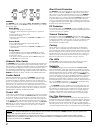
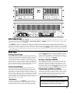
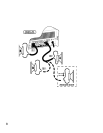
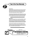
TAB
SLOT
YS#Z260 AirFlow Grille
YS#8807 Mounting Screw
YS# 8379 Foam Filter
Insert AirFlow Grille Tab
into Slot on Chassis first.
AP60xx AIR FILTER REPLACEMENT
and MAINTENANCE DIAGRAM
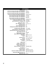
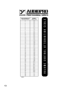
Both Channels Driven
Load
(OHMS)
1 KHz Cont.
Avg.
1 KHz Burst
4 1200 2000
2 2000 3600
All values are in WATTS. Measurements were made at the 0.1% distortion point. Some CONTIN-
UOUS AVERAGE POWER measurements required line currents greater than 30 Amps. The amplifier
under test was plugged into an IDEAL POWER LINE consisting of a REGULATED 120 VAC RMS 60
Hz pure sine wave. Ordinary AC "wall outlet" lines will always exhibit varying and unpredictable
amounts of sag. To produce objectively verifiable and accurate specifications these unknown factors
must be eliminated by using an ideal AC line. When using an ordinary elecrtical outlet, it will usually
be possible to get 3600 Watts when the AP6020 drives 2 ohms. The BURST measurements use a
10ms burst at 1Khz with 1/8 second pause between bursts. The 1Khz burst represents the maximum
possible sine wave output power.
Power Output