


1
Introduction
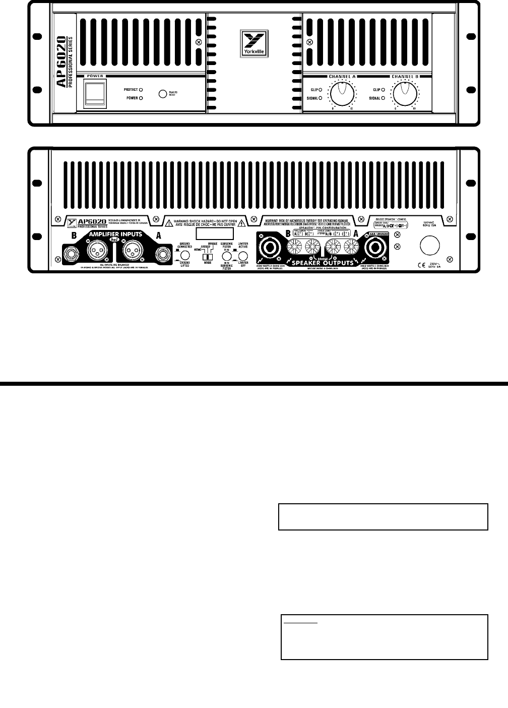
Your new Yorkville AP6020 power amplifier is designed and built to provide years of trouble free performance. The AP6020 combines the field
proven reliability of our Audiopro amplifiers with customer requested features such as switchable limiter, a Mono/Stereo/Bridge switch, and
SPEAKON™ output connectors as well as binding posts.
The AP6020 weighs a comfortable but solid 64 pounds, fits into three rack spaces, and reproduces music with over 7000 Watts of head-
room. It will drive reactive phase shifted loads with no difficulty - even though it is fully protected from accidental short circuits. Our design
goal was to create an amplifier that would do exactly what an amplifier should do: reproduce music with great power, complete reliability, and
uncompromising signal fidelity. We think you will agree that the Yorkville AP6020 does exactly that.
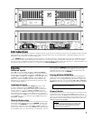
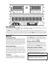
Inputs
Balanced Inputs
Either XLR or two–circuit ‘Ring, Tip, Sleeve’ Stereo 1/4” PHONE
cords may be used. Each channel’s XLR input is internally paralleled
with its phone input (The TIP of the channel ‘A’ PHONE input is con-
nected to pin 2 of its XLR input, the RING is connected to pin 3, and
the Sleeve is connected to PIN 1). PIN 2 is in phase, PIN 3 is 180
degrees out of phase, and PIN 1 is ground. We recommend using
balanced lines for the best hum-free performance, particularly when
chaining multiple amplifiers.
Unbalanced Inputs
Ordinary single circuit Standard 1/4” PHONE plugs may be used
to connect unbalanced signals. IMPORTANT NOTE: Such plugs
effectively connect the ring terminal to sleeve ground, so they work
correctly. However, if you use a Stereo 1/4” PHONE plug on an
unbalanced line, you MUST short the Ring terminal to the sleeve ter-
minal, otherwise the sensitivity will be 6dB lower than is specified!
(The same applies to the XLR input: To connect an unbalanced source
via the XLR input, you must connect the signal to Pin 2 and ground
BOTH Pin 1 and Pin 3).
Remote Referencing
You can approach balanced performance with unbalanced sources by
utilizing the remote reference feature of the AP6020. Connect a bal-
anced cable to the AP6020 just as you would if you were running a
balanced line. At the other end, connect Pin 3 and Pin 1 together, (or
connect ring to sleeve if you are using a PHONE plug cable), and plug
this modified end into your unbalanced piece of equipment. This con-
nection enables the AP6020’s input to look down the cable directly
at the output jack of the unbalanced equipment. Any hum voltage
generated across the cable’s impedance will be attenuated by the
common mode rejection of the AP6020.
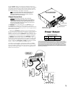
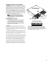
Driving Multiple AP6020’s
In large installations it is often desirable to operate many amplifiers in
tandem. Since each channel’s XLR input is internally paralleled with its
phone input, you may use the remaining input jack as an output to the
next amplifier. Obviously you will need both XLR to XLR and PHONE to
PHONE patch cords if you are going to tandem more than two amplifiers.
Ground Switch
Switching the ground switch on the rear panel will disconnect chas-
sis ground from circuit ground. Safety (earth) ground is still con-
nected to the chassis. We do not recommend lifting the ground strap
unless you are experiencing problems with ground loop hum in mul-
tiple amplifier setups where lifting the ground straps of all but one
amplifier cures the hum problem.
NOTE: These patch cords MUST be balanced whether
the input signal is balanced or unbalanced!
CAUTION: Sometimes hum problems are an indication of
improper AC wiring somewhere else in your system. Don’t
just doctor the symptom by lifting grounds. Fix the cause
by making sure that the proper electrical wiring safety
regulations have been adhered to.