


3
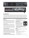
Clip LEDs
The Clip LEDs on the front panel will visibly indicate any signal
excursion beyond the dynamic headroom of the amplifier.
Reliability
The AP1020 is designed by Yorkville Sound. Each unit undergoes
a thorough, temperature cycled burn-in period, and each circuit is
tested by both manual and sophisticated computer-controlled equip-
ment, which is capable of identifying any deviation from the design
parameters. The design of the AP1020 is conservative, with respect to
the power handling capabilities of the output devices. The topology
guarantees that thermal stress, not secondary breakdown, will set the
limits of operation while the computer-optimized heat dissipation
system insures that excessive thermal stress will not occur.
The AP1020 is not only suitable for use in both heavy duty touring
sound reinforcement systems but also when high headroom and low
distortion are needed to fully reproduce the dynamic range and clar-
ity of today’s CD recordings. The AP1020 is built to survive grueling
road conditions and constant 2-ohm operation. Its reliability is a fixed
installation running 4 or 8-ohm studio monitors is without parallel.
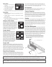
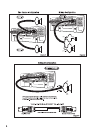
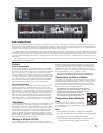
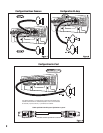
Output Connections
The AP1020 has 5-way binding posts and Neutrik four con-
tact Speakon™ connectors for output speaker connections.
Connection to the binding posts can either be made with a
banana plug inserted into the end of the post.
There are two Speakon™ connectors. The Speakons™ are con-
nected to the amplifier’s outputs whether the amplifier is in Stereo,
Mono or Bridge modes. Each Speakon™ output connector (Output
A and Output B) is wired in parallel with its respective binding posts
for two channel two cable connections (figure 1).
Speakon™ Output A also doubles as the A-B/Bridge connec-
tor. This Speakon™ contains both channels on one connector.
This is convenient when connecting one speaker to the amplifier
in bridge mode where the speaker is connected across the posi-
tives of each amplifier output. Configure the Mode switch for
Bridge and connect the speaker to pins +1 and +2 of the bridge/
biamp Speakon™ (figure 3).
To connect a biamp speaker, configure the amplifier for Stereo
and connect to the bridge/biamp connector but use all four ter-
minals in the Speakon™ connector which will connect A and B
Outputs separately to the speaker (figure 2). Connection configu-
rations are labeled on the back panel.
Impedance Mode Switch
The AP1020 comes factory-configured to deliver its maximum
power into a 2-ohm load. However, it is possible to switch your
AP1020 to deliver its maximum power into 4-ohms. The switch is
located on the rear panel above the line cord. To prevent damage
to the amplifier’s circuitry, only switch modes when the amplifi-
er’s power switch is off. This feature is meant to be used when the
speaker load is known. Please Note: In the 4-ohm configuration,
the minimum load per channel is 4-ohms. The minimum Bridge
load is 8-ohms. Attempting to operate into 2-ohm loads while in
the 4-ohm configuration will cause the amplifier to go into current
limit, thermal limit or both.
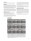
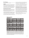
The Power specification chart in this manual shows the powers
that can be obtained for various configurations and loads.
1 kHz Burst
2-ohm Mode 2-ohm Mode 4-ohm Mode 4-ohm Mode
8 180 200 280 310
4 310 380 500 590
2 520 650 n/a n/a
2-ohm Mode 2-ohm Mode 4-ohm Mode 4-ohm Mode
8 165 250 250 290
4 270 350 400 560
2 400 600 n/a n/a
2-ohm Mode 2-ohm Mode 4-ohm Mode 4-ohm Mode
8 550 700 840 1100
4 840 1200 n/a n/a
2 n/a n/a n/a
All values are in Watts. Measurements were made at the 0.1% distortion point. Some continuous
average power measurements required line currents greater than 15 amps. The amplifier under test
was plugged into an ideal power line consisting of a Regulated 120 VAC RMS 60 Hz pure sine
wave. Ordinary AC wall-outlet lines will always exhibit varying and unpredictable amounts of sag.
To produce objectively verifiable and accurate specifications these unknown factors must be
eliminated by using an ideal AC line. When using an ordinary electrical outlet, it will usually be
possible to get 800 Watts when the AP1020 is bridged into 4-ohms. The burst measurement uses a
10 ms burst at 1 kHz with a pause of 1/8 second between bursts. The 1 kHz burst represents the
maximum possible sine wave output power.
One Channel Driven
Power Output
Load
(ohms)
1 kHz Cont.
Average
1 kHz Burst
1 kHz Cont.
Average
1 kHz Burst
Load
(ohms)
1 kHz Cont.
Average
1 kHz Burst
1 kHz Cont.
Average
1 kHz Burst
Load
(ohms)
1 kHz Cont.
Average
1 kHz Burst
1 kHz Cont.
Average
Both Channels Driven
Bridge Mode