


1
Introduction
Your new Yorkville AP1020 power amplifier has been designed and built to provide years of trouble free performance. The AP1020 starts
with the field-proven reliability of our Audiopro amplifiers and customer requested features like switchable limiters and a Mono/Stereo/Bridge
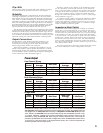
switch. We’ve made the AP1020 power configurable, (see Power Configuration), which makes it one of the most versatile amp in its class.
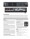
The AP1020 weighs a comfortable, but solid, 39 pounds; it fits into two rack spaces and reproduces music with over 1200 Watts of
headroom. It will drive reactive phase shifted loads with no difficulty - even though it is fully protected from accidental short circuits.
Our design goal was to create an amplifier, which would do exactly what an amplifier should do: reproduce music with great power,
complete reliability, and uncompromising signal fidelity. We think you will agree that the Yorkville AP1020 does exactly that. We hope
this manual will provide answers to any questions you may have about the features, controls, and characteristics of this amplifier.
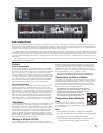
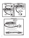
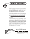
Inputs
Balanced Inputs
Either XLR or two circuit Ring, Tip, Sleeve stereo ¼-inch PHONE
cords may be used. Each channel’s XLR input is internally par-
alleled with its phone input: The Tip of the Channel A Phone
input is connected to pin 2 of its XLR input, the Ring is con-
nected to pin 3, and the Sleeve is connected to pin 1. Pin 2 is in
phase, pin 3 is 180 degrees out of phase, and pin 1 is ground.
We recommend using balanced lines for the best hum-free per-
formance, particularly when chaining multiple amplifiers.
Unbalanced Inputs
Ordinary single circuit standard 1/4 inch phone plugs may
be used to connect unbalanced signals. Important Note: Such
plugs effectively connect the ring terminal to sleeve ground,
so they work correctly. However, if you use a stereo ¼-inch
phone plug on an unbalanced line, you must short the ring ter-
minal to the sleeve terminal, otherwise the sensitivity will be 6
dB lower than is specified! (The same applies to the XLR input;
to connect an unbalanced source via the XLR input, you must
connect the signal to pin 2 and ground both pin 1 and pin 3).
Remote Referencing
You can approach balanced performance with unbalanced sources
by utilizing the remote reference feature of the AP1020 Connect a
balanced cable to the AP1020 just as you would if you were run-
ning a balanced line. At the other end, connect pin 3 and pin 1
together, (or connect ring to sleeve if you are using a phone plug
cable), and plug this modified end into your unbalanced piece of
equipment. This connection enables the AP1020’s input to “look”
down the cable directly at the output jack of the unbalanced equip-
ment. Any hum voltage generated across the cable’s impedance
will be attenuated by the common mode rejection of the AP1020.
Driving Multiple AP1020s
In large installations it is often desirable to operate many amplifi-
ers in tandem. Since each channel’s XLR input is internally paral-
leled with its phone input, you may use the remaining input jack
as an output to the next amplifier. Obviously you will need both
XLR-to-XLR and phone-to-phone patch cords if you are going to
tandem more than two amplifiers.
Note: These patch cords must be balanced whether the
input signal is balanced or unbalanced!
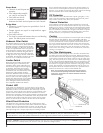
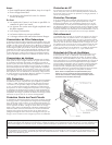
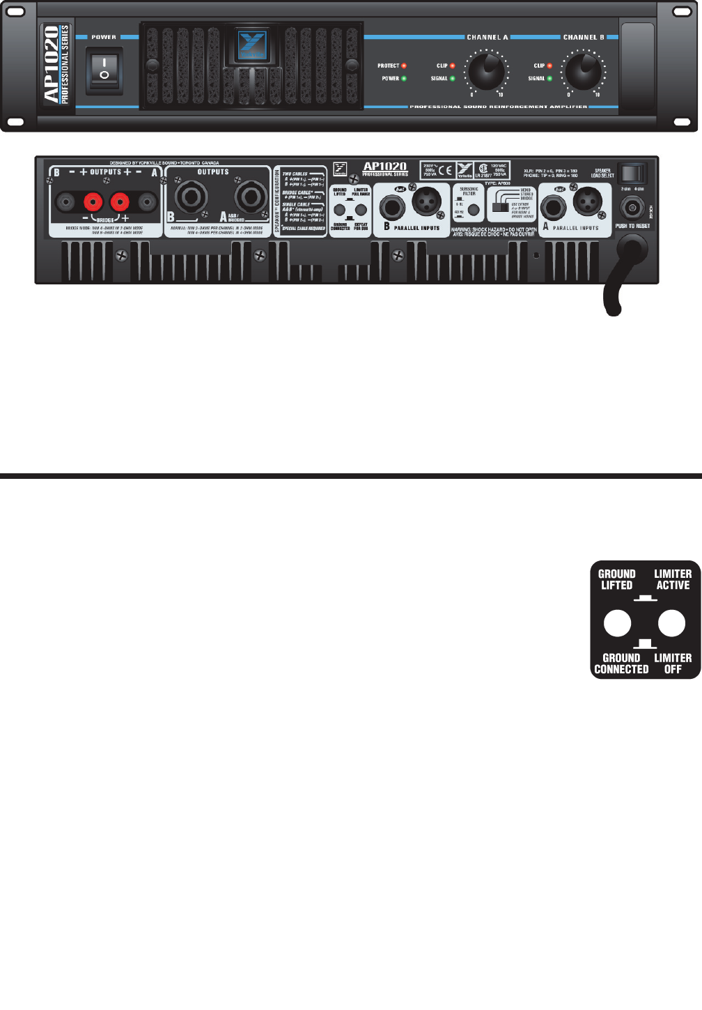
Ground Switch
Switching the ground switch on the rear
panel will disconnect chassis ground from
circuit ground. Safety (earth) ground is still
connected to the chassis. We do not rec-
ommend lifting the ground strap unless you
are experiencing problems with ground
loop hum in multiple amplifier setups
where lifting the ground straps of all but
one amplifier cures the hum problem.
CAUTION: Sometimes hum problems are an indication of
improper AC wiring somewhere else in your system. Don’t
just doctor the symptom by lifting grounds. Fix the cause by
making sure that the proper electrical wiring safety regula-
tions have been adhered to.
Modes
The AP1020 can be configured for dual-Mono, Stereo, or Bridged
Mono operation via this rear panel Mode switch. The following is
a description of each mode:
Mono Mode
• Channels A and B inputs are paralleled
• Each gain control adjusts the signal level for its
respective channel
• Output signals are of equal phase.
• Two loads are driven.
• Loads are connected between the black and red
post on each channel.