


10
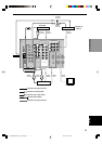
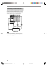
Connecting video components
Refer to the connection examples on the next page.
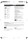
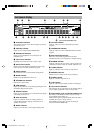
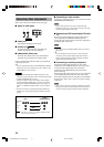
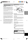
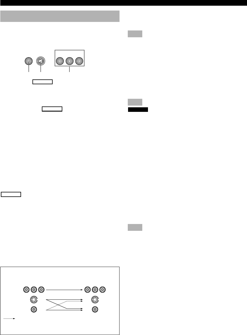
■ Types of video jacks
1 VIDEO jack
Conventional composite video signal.
2 S VIDEO jack
HTR-5650
Transmits color and luminance separately and
achieves high-quality color reproduction.
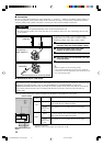
3 COMPONENT VIDEO jacks
Transmit color difference (P
B, PR) and luminance
separately and provide the best quality picture.
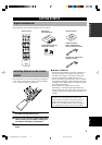
Use the commercially available cable type specified for
connecting each jack.
y
• You can designate the input for the COMPONENT VIDEO A
and B jacks to suit your components by using “INPUT 1 I/O
ASSIGNMENT” on the set menu.
HTR-5650
• Signals received through the S VIDEO input jacks can be
converted to composite signals in this unit and output through
its VIDEO MONITOR OUT as well.
• (With the exception of China and General models) Signals
received through the VIDEO jack on this unit can be output
through the S VIDEO MONITOR OUT jack by setting “V
CONV.” in “OPTION 1 DISPLAY SET” on the set menu to
ON.
• When the unit receives signals through both S VIDEO and
VIDEO jacks, signals input through the S VIDEO jack have
priority.
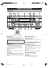
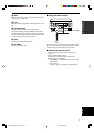
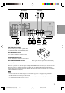
■ Connecting a video monitor
Connect the video input jack on your video monitor to the
MONITOR OUT VIDEO jack.
Note
• If you connect this unit with a source component using
Component video jacks, you also need to connect your video
monitor using Component video jacks.
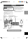
■ Connecting a DVD player/digital TV/cable
TV
Connect the optical digital audio signal output jack on
your component to the DIGITAL INPUT jack and
connect the video signal output jack on the component to
the VIDEO jack on this unit.
Note
HTR-5640
• The unit has only one DIGITAL INPUT jack, for use with a
DVD player.
y
• Use the AUDIO jacks on this unit for a video component
which does not have optical digital output jack. However,
multi-channel reproduction cannot be obtained with audio
signals input from the AUDIO jacks.
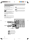
■ Connecting a recording component
Connect the audio signal input jacks on your video
component to the AUDIO OUT jacks on this unit. Then
connect the video signal input jack on the video
component to the VIDEO OUT jack on this unit for
picture recording.
Connect the audio signal output jacks on your component
to the AUDIO IN jacks on this unit. Then connect the
video signal output jack on the component to the VIDEO
IN jack on this unit to play a source from your recording
component.
Note
• Once you have connected a recording component to this unit,
keep its power turned on while using this unit. If the power is
off, this unit may distort the sound from other components.
Only when “V CONV.” in “OPTION 1 DISPLAY SET”
is set to ON on the set menu.
Output
(MONITOR OUT)
Signal flow inside this unit
Input
CONNECTIONS
COMPONENT VIDEO
P
R PB Y
S VIDEOVIDEO
1 2 3
HTR-5650
S VIDEO
VIDEO
COMPONENT
VIDEO
0103HTR5650/5640_09-18_EN-U.p65 02.12.24, 9:49 AM10