


Part Names and Functions
5
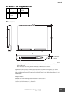
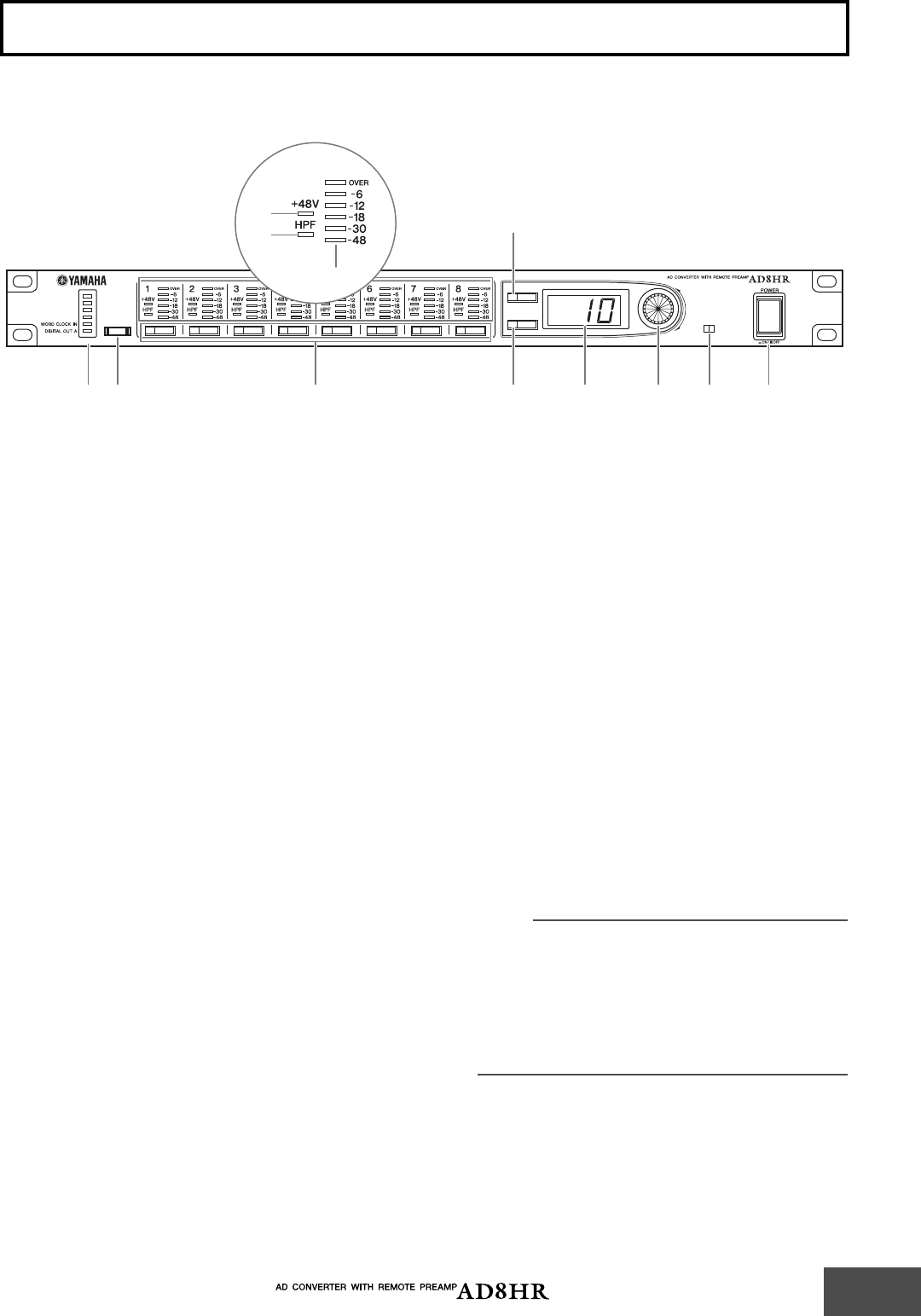
Front Panel
A
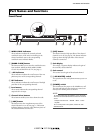
WORD CLOCK indicators
These indicators indicate the currently selected
wordclock source. If the unit is not locking to the
selected wordclock source, the corresponding
wordclock source indicator flashes.
B
[WORD CLOCK] button
This button enables you to select the wordclock source
from 44.1kHz, 48kHz, 88.2kHz, 96kHz, WORD
CLOCK IN, and DIGITAL OUT A (See page 7.)
C
+48V indicators
These indicators indicate the on/off status of the +48
phantom power of the corresponding channels.
D
HPF indicators
These indicators indicate the on/off status of the high
pass filter of the corresponding channels.
E
Level meters
These meters indicate the corresponding channel
output level in six steps.
F
Channel Select buttons
These buttons enable you to select channels to edit.
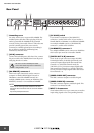
G
[+48V] button
This button turns the +48 phantom power of the
selected channels on or off (See page 7.) The button
indicator lights up when the +48V phantom power of
the selected channels is turned on.
H
[HPF] button
This button turns the high pass filter of the selected
channels on or off (See page 8.) The button indicator
lights up when the high pass filter of the selected
channels is turned on.
I
Gain display
This 3-digit, 7-segment display indicates the gain of
the currently selected channel.
J
Gain control
This control sets the gain of the selected channel.
K
[+48V MASTER] switch
This switch turns the +48V phantom master power on
or off.
L
[POWER] switch
This switch turns the power to the AD8HR on or off.
The gain and high pass filter settings are stored even
after you turn off the power to the unit.
NOTE:
To avoid loud noise from the speakers, turn on the power
first to the connected devices that are closest to the sound
source.
Example: Sound source
→
AD8HR
→
Mixer
→
Power
amplifier
To turn off the power to the system, reverse the order
described above.
Part Names and Functions
+48V
HPF
dB
96kHz
88.2kHz
48kHz
44.1kHz
+48V
OFF ON
MASTER
WORD CLOCK
12
7
6
8LKJ9
5
3
4