


14
Appendix
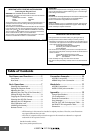
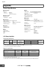
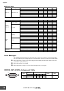
■ LED Level Meter
Error Messages
The AD8HR automatically diagnoses itself at the time of power up. If it detects a system abnormality,
one of the following error messages appears. If an abnormality is detected, consult your Yamaha dealer.
E1: The backup battery voltage is low. If the voltage is lowered further, the stored data will be erased. Ask
your dealer to replace the battery.
E2: The backup memory is corrupted.
E3: The backup battery voltage is very low and the backup memory is corrupted.
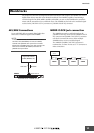
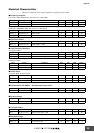
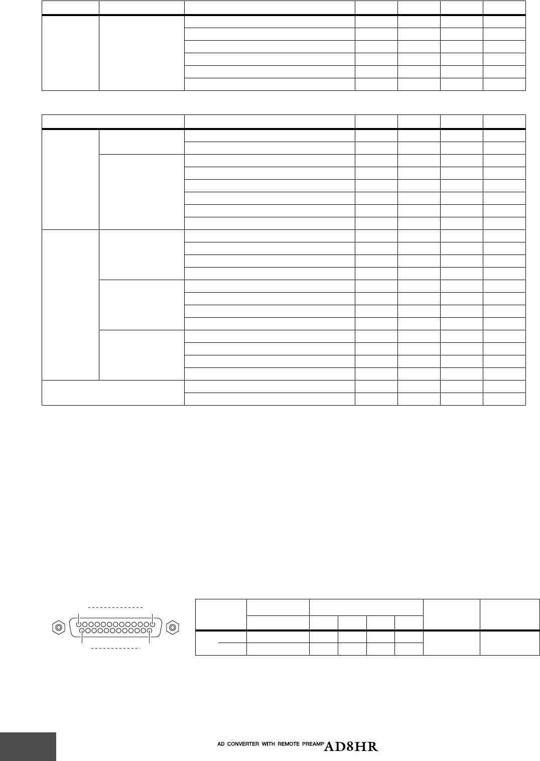
DIGITAL OUT A/B Pin Assignment Table
Input Output Conditions MIN TYP MAX UNITS
INPUT 1–8 DIGITAL OUT 1–8
OVER red LED: ON 0 dBFs
–6 amber LED: ON –6 dBFs
–12 amber LED: ON –12 dBFs
–18 amber LED: ON –18 dBFs
–30 green LED: ON –30 dBFs
–48 green LED: ON –48 dBFs
Parameter Conditions MIN TYP MAX UNITS
Sampling
Frequency
Frequency Range
Normal Rate 39.69 50.88 kHz
Double Rate 79.38 101.76 kHz
Jitter of PLL
DIGITAL IN fs=44.1kHz 10 ns
DIGITAL IN fs=48 kHz 10 ns
DIGITAL IN fs=39.69–50.88 kHz 20 ns
DIGITAL IN fs=88.2 kHz 10 ns
DIGITAL IN fs=96 kHz 10 ns
DIGITAL IN fs=79.38–101.76 kHz 20 ns
Internal
Clock
Frequency
word clock : int 44.1 kHz 44.1 kHz
word clock : int 48 kHz 48 kHz
word clock : int 88.2 kHz 88.2 kHz
word clock : int 96 kHz 96 kHz
Accuracy
word clock : int 44.1 kHz 50 ppm
word clock : int 48 kHz 50 ppm
word clock : int 88.2 kHz 50 ppm
word clock : int 96 kHz 50 ppm
Jitter
word clock : int 44.1 kHz 5 ns
word clock : int 48 kHz 5 ns
word clock : int 88.2 kHz 5 ns
word clock : int 96 kHz 5 ns
Signal Delay
analog input to digital output @fs=48 kHz 0.9 ms
@fs=96 kHz 0.45 ms
Signal
Data In Ch
*1
*1. Data In Ch can be received only on DIGITAL OUT A.
Data Out Ch
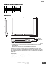
Open GND
1–2 1–2 3–4 5–6 7–8
Pin
Hot 1 5678
2, 3, 4, 9,11,
15, 16, 17
10, 12, 13,
22, 23, 24, 25
Cold 14 18 19 20 21
25
14
13
1